LSI design method

a design method and integrated circuit technology, applied in the direction of logic circuit coupling/interface arrangement, pulse technique, instruments, etc., can solve the problems of increasing difficulty in timing convergence, numerous repetition of layout design and verification, etc., and achieve the effect of shortening the tim

a design method and integrated circuit technology, applied in the direction of logic circuit coupling/interface arrangement, pulse technique, instruments, etc., can solve the problems of increasing difficulty in timing convergence, numerous repetition of layout design and verification, etc., and achieve the effect of shortening the tim

US20050278672A1Inactive Publication Date: 2005-12-15SOCIONEXT INC

Image

  • LSI design method
  • LSI design method
  • LSI design method

Examples


Embodiment Construction

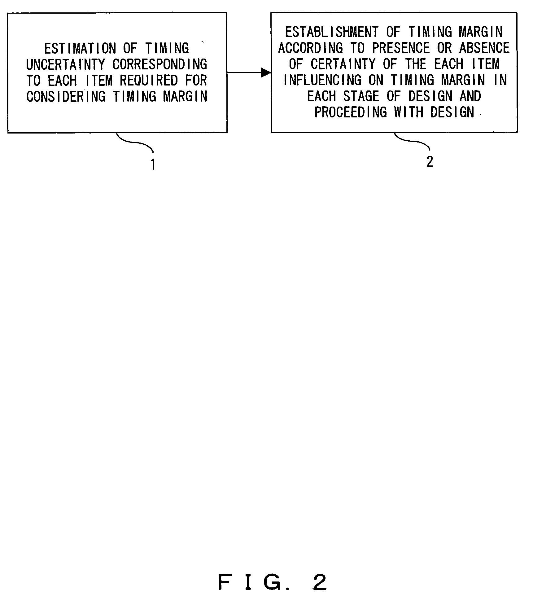
[0026]FIG. 2 shows a fundamental functional block chart of an LSI design method according to the present invention. In FIG. 2, first, step 1 estimates the timing uncertainty brought by the uncertain influences given by every item that has to be considered according to the establishment of the timing margin in an early stage of LSI design. And step 2 establishes a timing margin in each design stage of the LSI design based on the estimation result of the timing uncertainty, depending on whether or not an influence of the each item on timing has been determined. Then designs of each stage are carried out accordingly. In the present embodiment according to the invention, a timing uncertainty can also be estimated based on a condition of a product specification, an operating condition and a sign-off condition of an LSI in the step of the timing uncertainty estimation 1.

[0027] Also, in the estimation of a timing uncertainty influenced by a “Clock Skew” as one of items required for consid...


PUM


Abstract

An LSI design method according to the present invention is to estimate a timing uncertainty in an early stage of design for each item of which an influence on timing is uncertain among respective items requiring consideration relating to establishment of timing; and define a timing margin in each design stage by using the timing uncertainty estimation result depending on whether or not an influence of the each item on timing has been determined, followed by proceeding with the design in the respective design stages accordingly. As such, according to the present invention, a timing uncertainty is estimated in an early stage of LSI design, followed by proceeding with the design by using the timing uncertainty as required.

Description

CROSS-REFERENCE TO RELATED APPLICATIONS [0001] This application is based upon and claims the benefit of priority from the prior Japanese Patent Application No. 2004-174722, filed in Jun. 11, 2004, the entire contents of which are incorporated herein by reference. BACKGROUND OF THE INVENTION [0002] 1. Field of the Invention [0003] The present invention relates to a design method for a semiconductor integrated circuit, specifically to a design method for LSI in which an uncertain amount of timing is adjusted while eliminating factors relative to determined timings during a design process thereof. [0004] 2. Description of the Related Art [0005] In recent years, the design of a semiconductor integrated circuit is required for consideration of influences by an on-chip variation and a cross-talk, besides LSI for use in high speed operations, a convergence of timing has been increasingly difficult. This makes it important to establish an uncertain amount of timing (“timing uncertainty” her...

Claims


Application Information

Patent Timeline
15 Dec 2005
Publication
US20050278672A1
IPC
G06F17/50; H01L21/82; H03K19/00; H03K19/0175
CPC
G06F17/505; G06F30/327
Inventors
HOSONO, TOSHIKATSU; YONEDA, TAKASHI