
Wire-guiding structure of a shuttle of a sewing machine

a technology of shuttles and wires, which is applied in the manufacture of coils, sewing apparatuses, textiles and paper, etc., can solve the problems of reducing the winding efficiency, reducing the number of wires that can be collected in the wire-winding wheel in the casing, and reducing the number of users, so as to achieve the effect of greatly increasing the number of wires supplied to the shuttl

Inactive Publication Date: 2005-12-22
CHIEN CHIH I
View PDF6 Cites 10 Cited by
  • Summary
  • Abstract
  • Description
  • Claims
  • Application Information

AI Technical Summary

Benefits of technology

[0005] Accordingly, the primary object of the present invention is to provide a wire-guiding structure of a shuttle of a sewing machine, wherein wire supplied to the shuttle is increased greatly and the wire can be successfully supplied to the sewing machine by using a wire-guiding rod.
[0006] To achieve above objects, the present invention provides wire-guiding structure of a shuttle of a sewing machine, wherein one end surface of the shuttle is formed with a wire-receiving hole for supplying wire continuously. Wire for seaming is supplied to the interior of the shuttle from an external larger scale wire-winding and the wire is wound around the wire-winding wheel for outputting. It is unnecessary to update the shuttle so as to increase the finishing efficiency. Furthermore, the end surface of the shuttle is installed with a wire-guiding rod for guiding wire successfully so that the wire can run along a predetermined path efficiently. Thus wire can be supplied successfully. Moreover, a wire-winding wheel is installed in the shuttle so that wire will be easily wound around the wire-winding wheel smoothly. Thus wire is supplied to the sewing machine successfully.

Problems solved by technology

However, amount of wire capable being collected in the wire-winding wheel in the casing is limited.
However, this will reduce the winding efficiency.
This is a tedious work to the users.
Above mentioned defect especially occurs at a large scale sewing machine with a great amount of shuttles.
Thereby, much labor is required, efficiency is low and cost is increased.

Method used


Image

  • Wire-guiding structure of a shuttle of a sewing machine
  • Wire-guiding structure of a shuttle of a sewing machine
  • Wire-guiding structure of a shuttle of a sewing machine

Examples


Embodiment Construction

[0015] In order that those skilled in the art can further understand the present invention, a description will be described in the following in details. However, these descriptions and the appended drawings are only used to cause those skilled in the art to understand the objects, features, and characteristics of the present invention, but not to be used to confine the scope and spirit of the present invention defined in the appended claims.

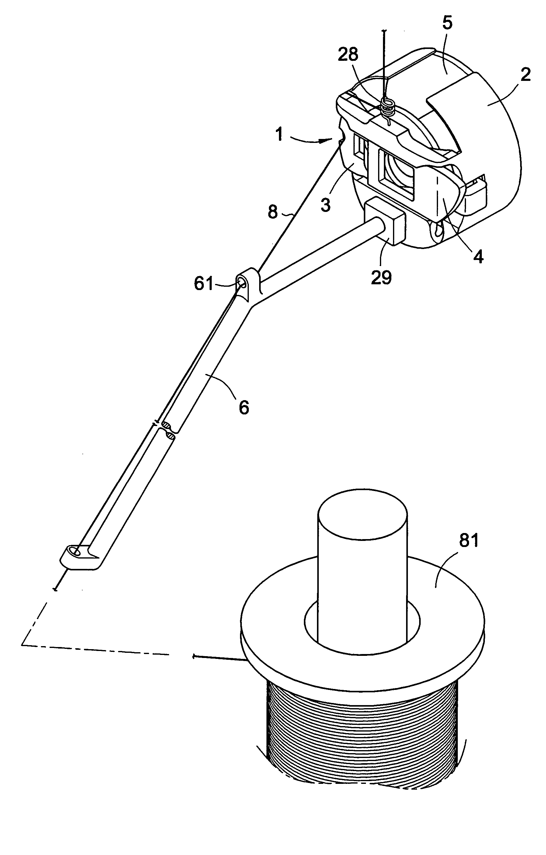
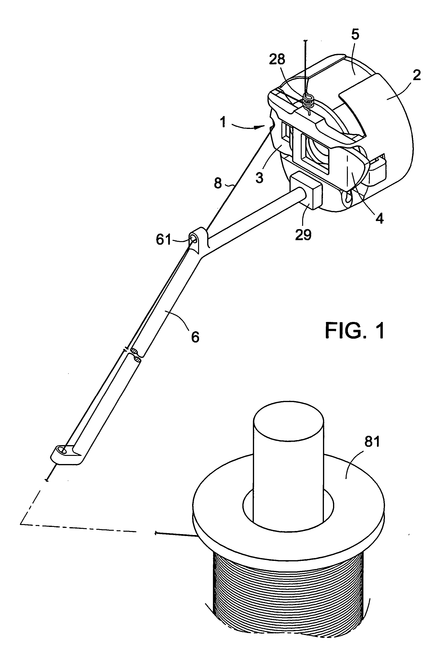
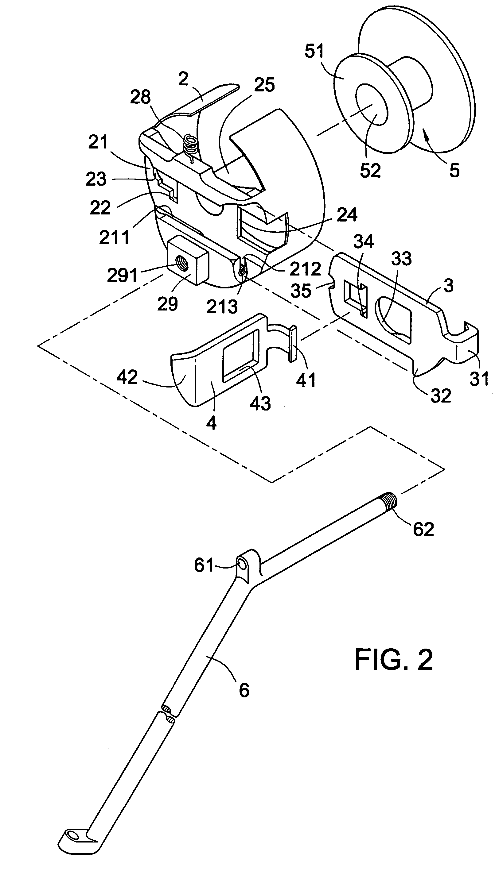
[0016] With reference to FIG. 2, an exploded perspective view of the wire-guiding structure of a shuttle of a sewing machine according to the present invention is illustrated. The wire-guiding structure includes a casing 2, an engaging sheet 3 which is combined with the casing 2 so as to form a wire-receiving hole 11; a buckle 4 for buckling the engaging sheet 3 to the casing 2, a wire-winding wheel 5 for winding a wire 8 successfully, and a wire-guiding rod 6 for guiding the wire 8 (referring to FIG. 1). By above mentioned structure, the wire i...


PUM


Abstract

A wire-guiding structure of a shuttle of a sewing machine is disclosed. One end surface of the shuttle is formed with a wire-receiving hole for supplying wire continuously. A wire for seaming is supplied to an interior of the shuttle from an external larger scale wire-winding and the wire is wound around the wire-winding wheel for outputting. It is unnecessary to update the shuttle so as to increase the finishing efficiency. Furthermore, the end surface of the shuttle is installed with a wire-guiding rod for guiding wire successfully so that the wire can run along a predetermined path efficiently. Thus wire can be supplied successfully. Moreover, a wire-winding wheel is installed in the shuttle so that wire will be easily wound around the wire-winding wheel smoothly. Thus wire is supplied to the sewing machine successfully.

Description

FIELD OF THE INVENTION [0001] The present invention relates to wire-windings of shuttles, and particular to a wire-guiding structure of a shuttle of a sewing machine so that the wire is supplied to the shuttle continuously by using a wire-guiding rod. BACKGROUND OF THE INVENTION [0002] Shuttles of sewing machines are wire collectors for supplying seaming wires. The shuttles are pivotally installed to rotary seats on needle guiding paths of sewing machines. In seaming, the wired needles will hook wires on the shuttles as the needles are inserted into cloths. [0003] The prior art shuttle has a casing and a wire-winding wheel pivotally installed within the casing. Before use, wire is wound around the wire-winding wheel and then the wire-winding wheel is placed in the casing. The shuttle is then placed on the rotary seat in the needle guiding path of sewing machine for assuring that the wire can be normally supplied. However, amount of wire capable being collected in the wire-winding wh...

Claims


Application Information

Patent Timeline
IPC IPC(8): B65H81/02D05B57/14D05B59/00H01F41/08
CPCD05B59/00
Inventor CHIEN, CHIH-I
Owner CHIEN CHIH I
Learn More