Pressure control system

a control system and pressure control technology, applied in the field ofsemiconductor processing, can solve the problems of limiting the rate at which gas can exit the chamber, undesirable turbulence or stirring of particles, and the addition of additional, relatively complex and expensive components of the mass flow controller

Active Publication Date: 2005-12-22
ASM INTERNATIONAL
View PDF12 Cites 160 Cited by
  • Summary
  • Abstract
  • Description
  • Claims
  • Application Information

AI Technical Summary

Problems solved by technology

Such turbulence or stirring up of particles is undesirable because these events can contaminate or otherwise adversely affect the quality of the process results on the substrates.
First, the pump-down is started through a small orifice valve, a so-called “slow-pump valve,” which, because of the small size of the valve's opening, limits the rate at which gas can exit

Method used


Image

  • Pressure control system
  • Pressure control system
  • Pressure control system

Examples


Embodiment Construction

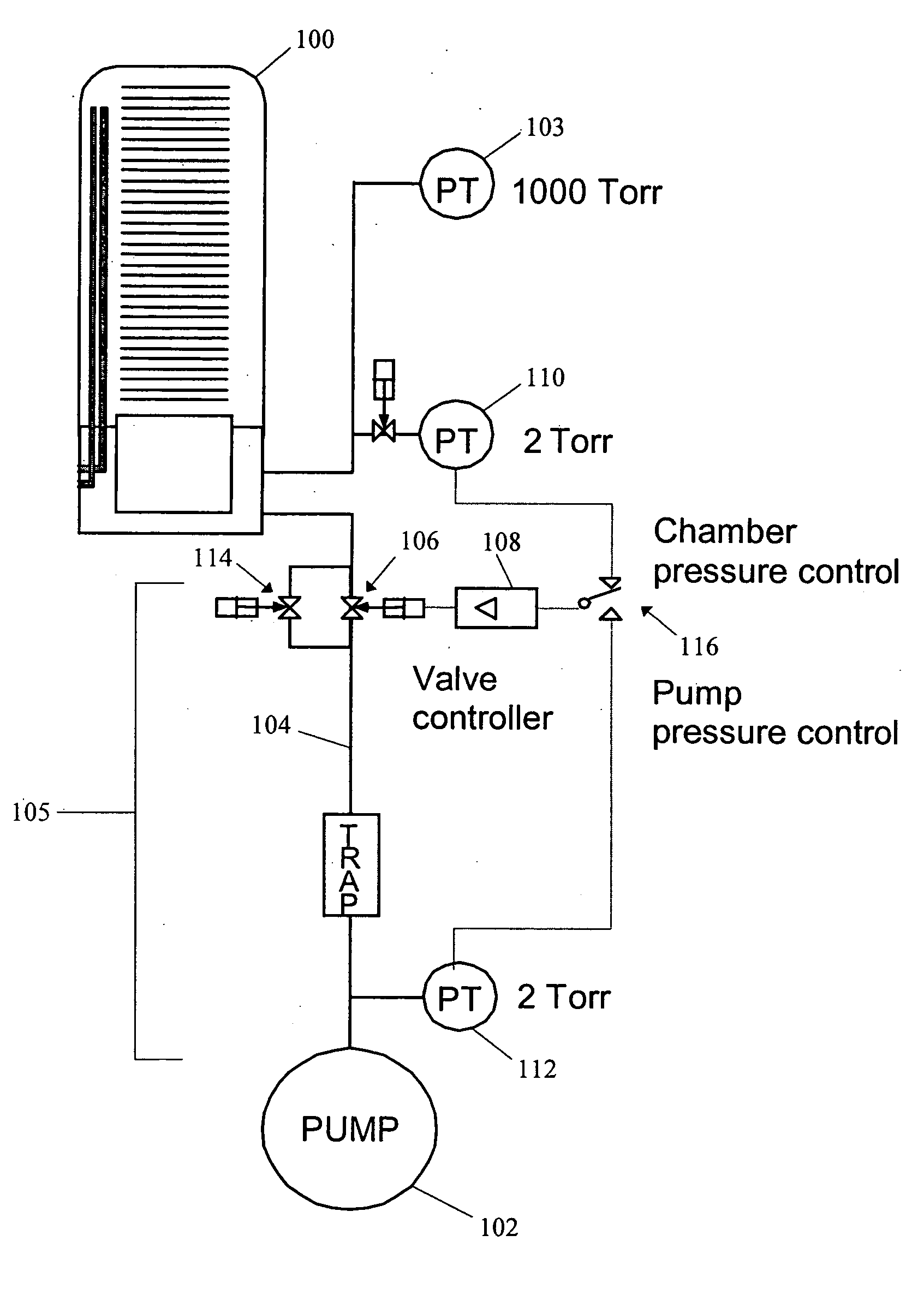
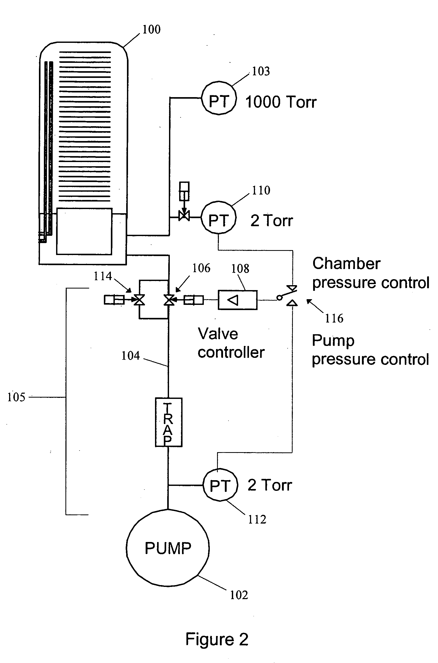
[0018] As noted above, the evacuation, or pump-down, of a process chamber involves balancing the conflicting requirements of minimizing gas flow turbulence and particle agitation while maximizing process chamber utilization for substrate processing. It has been found that an optimal solution for reconciling these conflicting goals can be balanced by using a system capable of achieving a controlled mass flow rate during evacuation of the chamber. By having gas exit the process chamber at a roughly steady rate, turbulence and particle agitation caused by sudden changes in gas flow rates can be reduced. Moreover, the constant mass flow allows a set volume of gas to be consistently withdrawn, allowing the chamber to be pumped down more quickly than if the mass flow were allowed to decrease as the pressure in a process chamber decreases. It will be appreciated that such a mass flow decrease can occur where a valve allowing gas to flow out of a chamber has a constant sized opening.

[0019]...


PUM

PropertyMeasurementUnit
Fractionaaaaaaaaaa
Fractionaaaaaaaaaa
Fractionaaaaaaaaaa

Abstract

A pressure control system allows gas to be evacuated out of a semiconductor process chamber at a substantially constant rate of mass flow. A gas line connects the process chamber to a vacuum pump. A controllable valve having a variable sized opening is positioned between the process chamber and the vacuum pump. A pressure sensor is in turn positioned between the valve and the vacuum pump, proximate the inlet to the vacuum pump. The size of the variable sized opening is regulated based upon the pressure in the gas line measured by the pressure sensor. The size of the valve opening is varied to maintain the pressure measured by the pressure sensor at a constant value. As a result, because the quantity of gas flowing through the gas line is proportional to the gas pressure, a substantially constant mass flow of gas out of the chamber and into the pump can be achieved.

Description

BACKGROUND OF THE INVENTION [0001] 1. Field of the Invention [0002] This invention relates generally to semiconductor processing and, more particularly, to pressure control systems for process chambers. [0003] 2. Description of the Related Art [0004] Many semiconductor fabrication processes, or processes for fabricating integrated circuits, require that the pressure within a process chamber be varied between relatively high and relatively low pressures. For example, a chamber might be at, e.g., atmospheric pressure, for loading a semiconductor substrate into the chamber and then the chamber is pumped down or evacuated to a relatively low pressure, e.g., a vacuum, for processing of the substrate. When pumping down a process chamber from the relatively high pressure to the relatively low pressure, the pump-down rate is preferably not so large as to cause undesirable turbulence, which can stir up particles within the process chamber or within the piping network attached to the process ...

Claims


Application Information

Patent Timeline
IPC IPC(8): C23C16/44C23F1/00G05D7/01G05D16/20H01L21/00H01L21/306
CPCC23C16/4412H01L21/67253H01L21/67017G05D16/208
Inventor SNIJDERS, GERT JAN
Owner ASM INTERNATIONAL
Why Eureka
Try Eureka