
Eureka
For R&D, Eureka makes reading and utilizing patents & technical documents easy.
Eureka AIR
Designed for self-driven R&D workflows. Generate viable solutions, solve complex R&D challenges, empower your innovation with AI.

Eureka Materials
Designed for material experts only. Revolutionize your material R&D, from search, analyze, to developing new materials.

TechResearch
Generate reliable direction feasibility study reports for your R&D in just a few steps.

TechSeek
Discover and master advanced knowledge NOW. Basics, ideas, possibilities, all at once.

TechMind
As an expert in R&D Theories, TechMind can generates customized viable solutions instantly.

TechRisk
Analyze your overall solution with one click, know your potential R&D risks in advance.

TechMonitor
Get weekly tech updates, stay abreast of the latest tech innovations and key insights.
Simple ahdesive tape cutter
- Summary
- Abstract
- Description
- Claims
- Application Information
AI Technical Summary
Benefits of technology
Problems solved by technology
Method used
Image

Examples
first embodiment
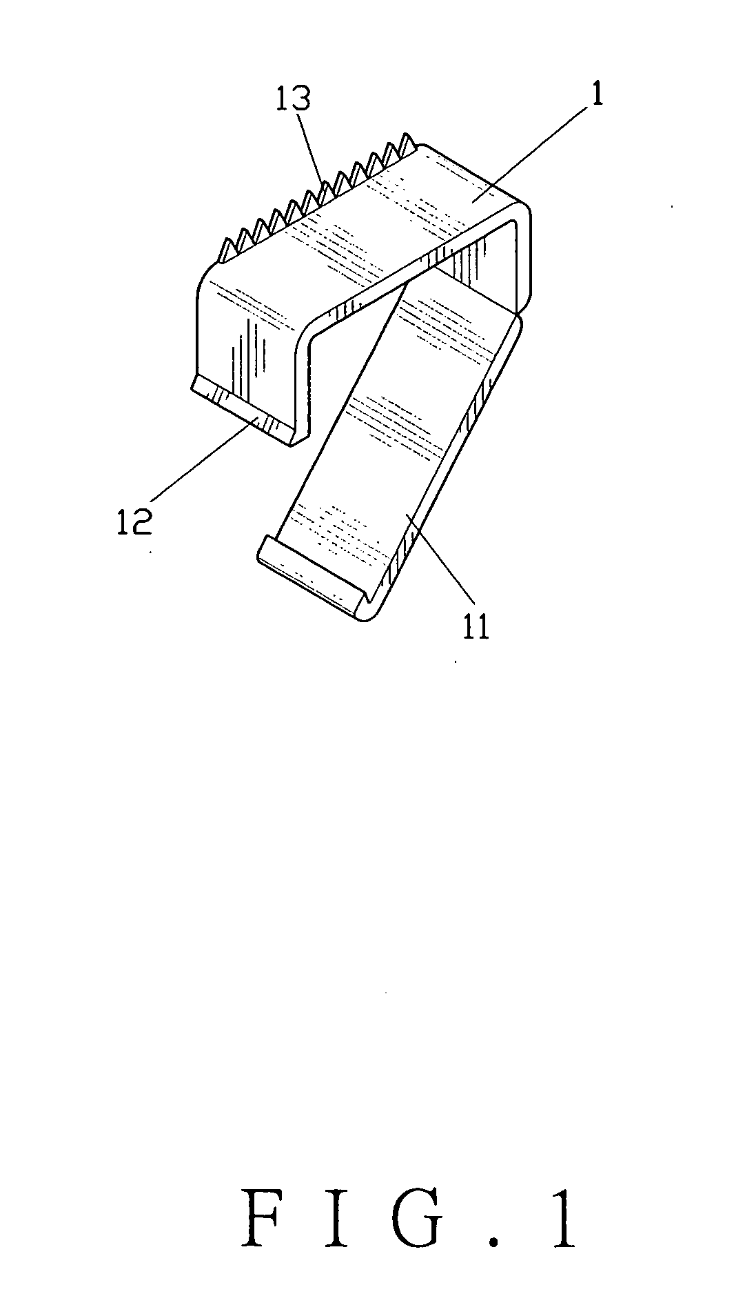
[0022] Referring to FIG. 1 showing a first embodiment according to the invention, the invention comprises a cutter seat 1, which has an elastic and flexible fastening section 11 at a lower side portion thereof in a bent manner, with the fastening section 11 as a formed integral with the cutter seat 1 or pivotally connected to the cutter seat 1; a fastening member 12 at an edge of the other side thereof; and a row of sawteeth 13 at one edge of an upper surface thereof.
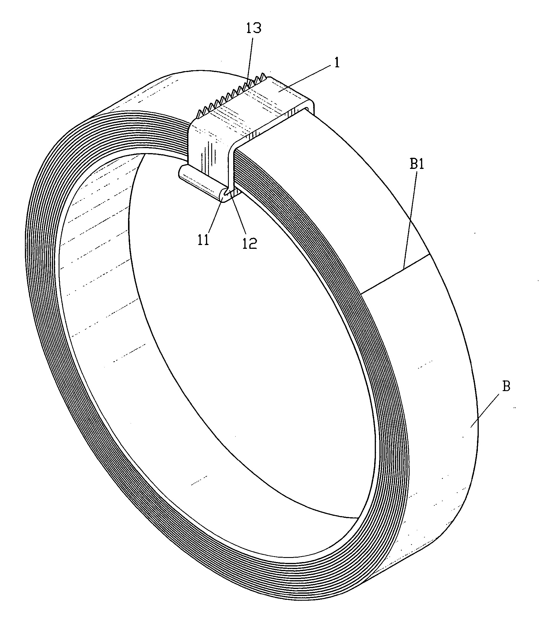
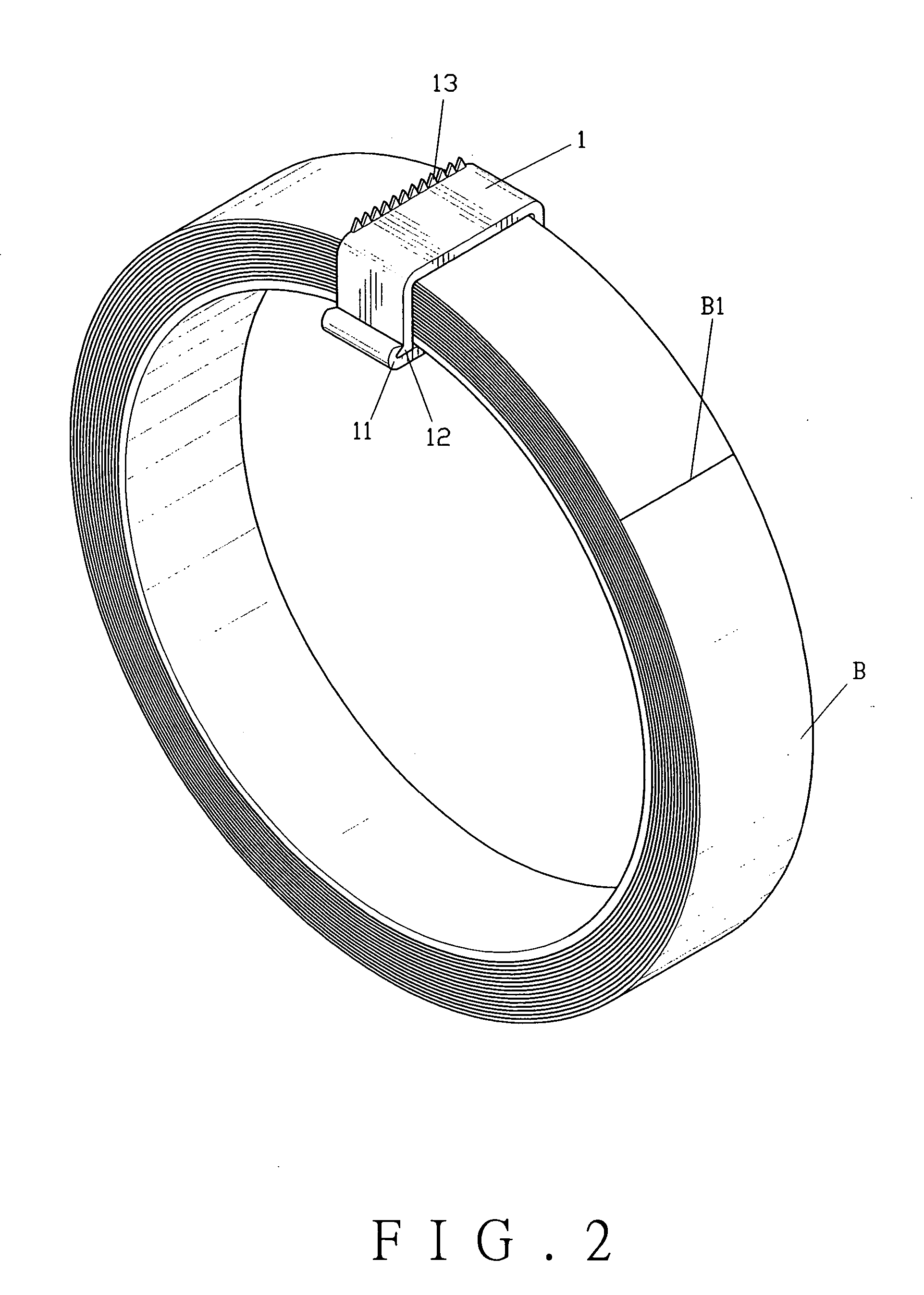
[0023] To put the aforesaid structure to use, referring to FIG. 2, the fastening section 11 at one side of the cutter seat 1 is bound around an adhesive tape roll B, and the fastening section 11 is fastened with the fastening member 12, such that the cutter seat 1 stays mobile around the adhesive tape B. To cut the adhesive tape, the cutter seat 1 is moved at the adhesive tape roll B, and an edge with the sawteeth 13 of the cutter seat 1 is butted against a cut-off end B1 of the adhesive tape roll B. An appropriate leng...
second embodiment
[0024] Referring to FIG. 4 showing a second embodiment according to the invention, the invention comprises a cutter seat 2, which has two elastic and flexible fastening sections 21 and 22 at two lower sides thereof, and a row of sawteeth 23 at one edge of an upper surface thereof. To put the structure to use, referring to FIG. 3, the two fastening sections 21 and 22 of the cutter seat 2 are bound around two sides of the adhesive tape roll B. Using elasticity and flexibility of the cutter seat 1, the fastening sections 21 and 22 are fastened around the adhesive tape B in a mobile manner. To cut off the adhesive tape, the cutter seat 1 is moved at the adhesive tape roll B, and an edge with the sawteeth 13 of the cutter seat 1 is butted against the cut-off end B1 of the adhesive tape roll B. An appropriate length of adhesive tape to be cut off is picked, and the cut-off end B1 of the adhesive tape is pressed downward as shown in FIG. 3, thereby quickly and readily cutting off the adhes...
third embodiment
[0025] Referring to FIG. 5 showing a third embodiment according to the invention, the invention comprises a cutter seat 3, which has two elastic and flexible fastening sections 31 and 32 at two lower side portions thereof, and a row of sawteeth 33 at one edge of an upper surface thereof. The cutter seat 3 is especially devised as having an arched sectional area for adapting to adhesive tapes having different shapes. The embodiment according to the invention has a unique design and provides esthetical values for increasing selling points and promoting sales quantity, while also accomplishes quickly and readily cutting off an adhesive tape.
PUM
 Abstract
Description
Claims
Application Information
 - R&D Engineer
- R&D Manager
- IP Professional
- Industry Leading Data Capabilities
- Powerful AI technology
- Patent DNA Extraction
Browse by: Latest US Patents, China's latest patents, Technical Efficacy Thesaurus, Application Domain, Technology Topic, Popular Technical Reports.
© 2024 PatSnap. All rights reserved.Legal|Privacy policy|Modern Slavery Act Transparency Statement|Sitemap|About US| Contact US: help@patsnap.com