
Driving state determining system

a technology of driving state and determining system, which is applied in the direction of vehicular safety arrangements, pedestrian/occupant safety arrangements, instruments, etc., can solve the problems of system not functioning for a purpose, force braking force, and occupant discomfort, and achieve the effect of reducing the risk of rear-end collision

Inactive Publication Date: 2005-12-22
DENSO CORP
View PDF8 Cites 46 Cited by
  • Summary
  • Abstract
  • Description
  • Claims
  • Application Information

AI Technical Summary

Benefits of technology

[0007] It is an object of the present invention to provide a driving state determining system to solve the above problem. The system determines a present driving state as one of multiple danger states and causes a driver to recognize one of the danger states and thereby rapidly conduct operation for preventing the corresponding danger state.

Problems solved by technology

Further, stepping of a braking pedal is detected to cause an enforced braking force.
A conventional safety system such as the above works after a collision with an obstruction is determined to be unavoidable.
Therefore, the system does not function for a purpose that a driver recognizes a danger beforehand to thereby conduct an operation for preventing the accident from occurring.
Activating this safety system may give an occupant discomfort or involve a rear-end collision with a following vehicle.
Therefore, the system only responds to an obstruction (a preceding vehicle, an on-road obstruction, or an oncoming vehicle) ahead of the subject vehicle, which is limited to uses in straight roads.

Method used


Image

  • Driving state determining system
  • Driving state determining system
  • Driving state determining system

Examples


Embodiment Construction

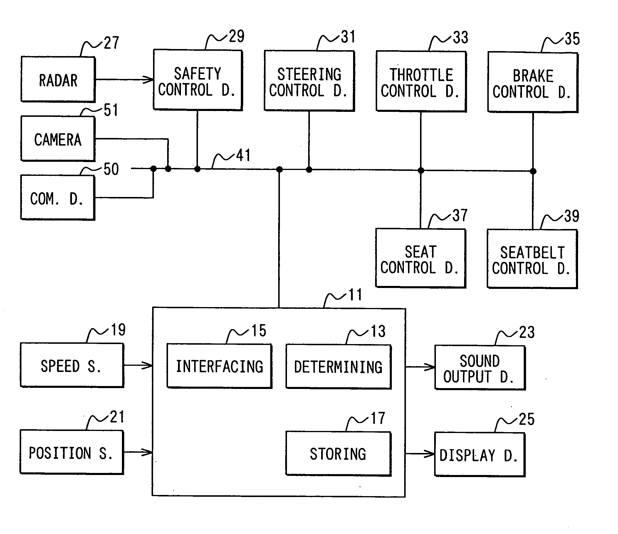
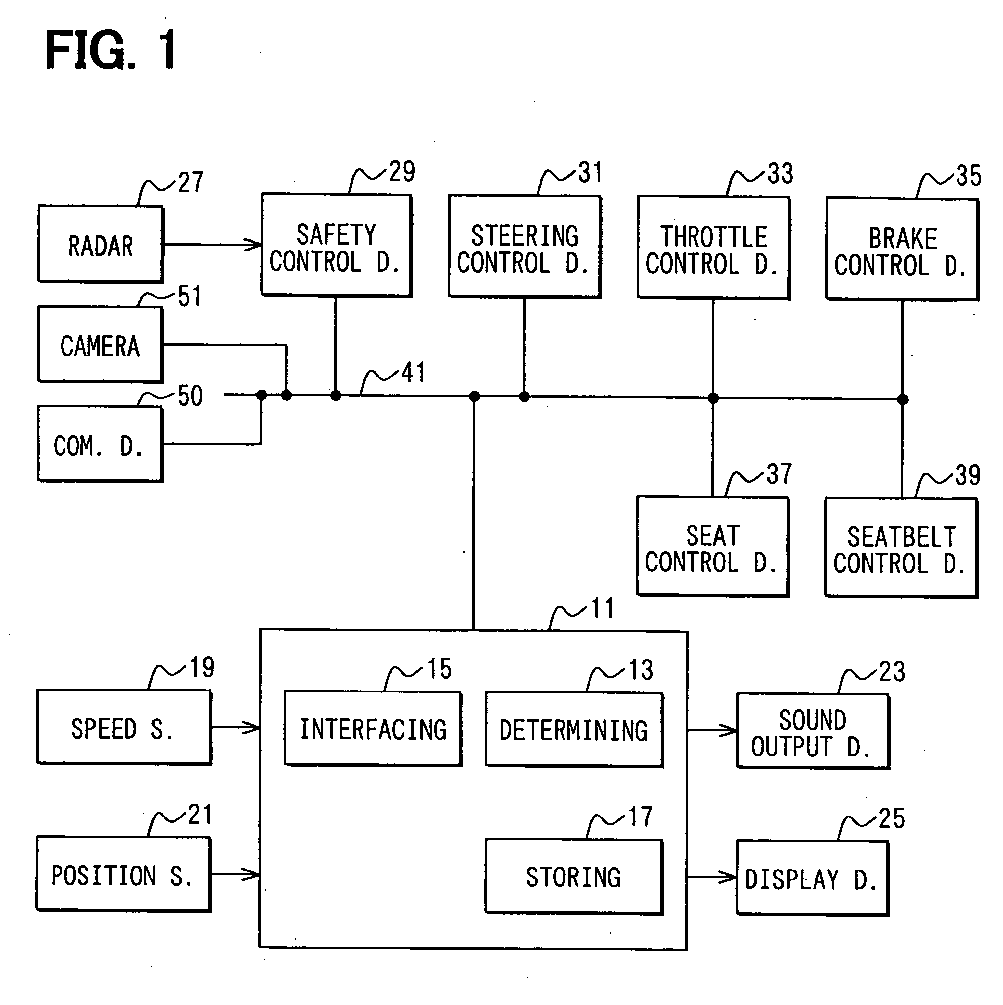
[0019] A driving state determining system according to an embodiment of the present invention is adapted to a navigation device 11. FIG. 1 shows a block diagram of the navigation device 11 and its peripheral devices, all of which are mounted in a subject vehicle. The navigation device 11 connects with a speed sensor 19, a position sensor 21, a sound output device 23, a display device 25, and an in-vehicle LAN 41.

[0020] The speed sensor 19 is disposed in a hub of a wheel assembly or the like to detect a vehicle speed and output a detection result to the navigation device 11. The position sensor 21 includes a GPS (Global Positioning System) antenna, and a gyroscope to output to the navigation device 11 information necessary for computing a present position or information enabling understanding of driving states of the subject vehicle. The sound output device 23 includes a speaker and an amplifier to output sounds based on signals from the navigation device 11. The display device 25 i...


PUM


Abstract

A driving state determining system in a vehicle recognizes an obstruction that may collide with the vehicle based on obtained various information. The system executes a plurality of danger determinations that have individual determination conditions, based on a relative distance and a relative speed with the obstruction to thereby comprehensively determine one of danger regions that the vehicle is situated in. The danger regions are classified depending on a danger degree. The system then outputs a determined result to relevant devices. Each of the relevant devices thereby determines operation by obtaining the comprehensively determined result outputted by the system. Consequently, the relevant devices can function more cooperatively and more effectively to lead to increase in safety than another system where each of relevant devices determines operation by individually collecting information.

Description

CROSS REFERENCE TO RELATED APPLICATIONS [0001] This application is based on and incorporates herein by reference Japanese Patent Application No. 2004-178581 filed on Jun. 16, 2004. FIELD OF THE INVENTION [0002] The present invention relates to a driving state determining system that determines driving states based on information from various in-vehicle sensors or the like to thereby output determination results. BACKGROUND OF THE INVENTION [0003] A safety system called Pre-Crash Safety System starts to come into practical use. This system determines beforehand a subject vehicle's state where a collision is unavoidable to thereby promptly activate safety equipment for decreasing collision damage (refer to Patent Document 1). In detail, a detector such as a millimeter wave radar detects a position, a distance, a speed, or the like of an obstruction ahead of a subject vehicle. When it is determined that collision with this obstruction is unavoidable, a seatbelt for a driver's seat or a...

Claims


Application Information

Patent Timeline
Patent Type & Authority Applications(United States)
IPC IPC(8): B60Q1/00B60Q1/52B60R21/00B60R22/46B60T7/22B60T8/32B60W40/02G06F7/00G08G1/16
CPCB60Q9/008B60T7/22B60T2201/02B60W50/16B60W10/18B60W30/08B60W40/02B60T2201/022
Inventor KUBO, SHUNITSU
Owner DENSO CORP
Features
  • Generate Ideas
  • Intellectual Property
  • Life Sciences
  • Materials
  • Tech Scout
  • Unparalleled Data Quality
  • Higher Quality Content
  • 60% Fewer Hallucinations
Learn More