Antenna

a technology of antennas and antennas, applied in the direction of resonant antennas, elongated active element feeds, radiating element structural forms, etc., can solve the problems of antennas being forced to limit the mounting place of antennas or designs, the impedance of antennas becoming smaller, and the antennas being obliged to limit the mounting place of antennas. , to achieve the effect of high precision antennas, low cost and broadband

Inactive Publication Date: 2005-12-22
PANASONIC CORP
View PDF6 Cites 62 Cited by
  • Summary
  • Abstract
  • Description
  • Claims
  • Application Information

AI Technical Summary

Benefits of technology

[0014] wherein the second antenna element has a first end coupled to a second end of the first antenna element, a second end coupled to the ground plate, and an intermediate section formed above the ground plate is folded in plural times. Folding in plural times of the intermediate sections of both the first and the second elements allows overall lengths of respective antenna elements to be a 5 / 4 wavelength, so that the antenna elements can work in a ¼ wavelength mode. This construction allows the respective antenna elements to be low-profiled, so that a compact antenna is obtainable.
[0015] An antenna of the present invention may include a parasitic antenna element of which intermediate section is shaped like that of a first antenna element or a second antenna element. This parasitic antenna element is excited in-phase with the first and the second antenna elements, so that the antenna can broaden its frequency band.
[0016] An antenna of the present invention may include holders and supports made of a dielectric substrate. A first antenna element or a second antenna element is formed into a predetermined pattern on the dielectric substrate. The printed wiring boards can form the holders and the supports, and the metal layer of the printed wiring board can form the first, second, and parasitic antenna elements. As a result, a high precision antenna can be formed at an inexpensive cost. And according to requested antenna performance, an antenna having various patterns can be easily manufactured.
[0017] An antenna of the present invention may include holders and supports made from sheet boards. The holders, first and second antenna elements as well as the supports and parasitic antenna elements can be manufactured consecutively like a sheet, so that the antenna is obtainable at an inexpensive cost.
[0018] As discussed above, according to the present invention, the intermediate section of respective antenna elements are folded in plural times, thereby lowering the height of the antenna elements. As a result, a compact antenna is obtainable.

Problems solved by technology

If height “H” of an antenna element is shortened to a height lower than a ¼ wavelength of the operating frequency, the antenna impedance becomes smaller and it is difficult to obtain an impedance matching.
As a result, these types of antennas are obliged to limit a mounting place of the antenna or a design of a car body.

Method used


Image

  • Antenna
  • Antenna
  • Antenna

Examples


Embodiment Construction

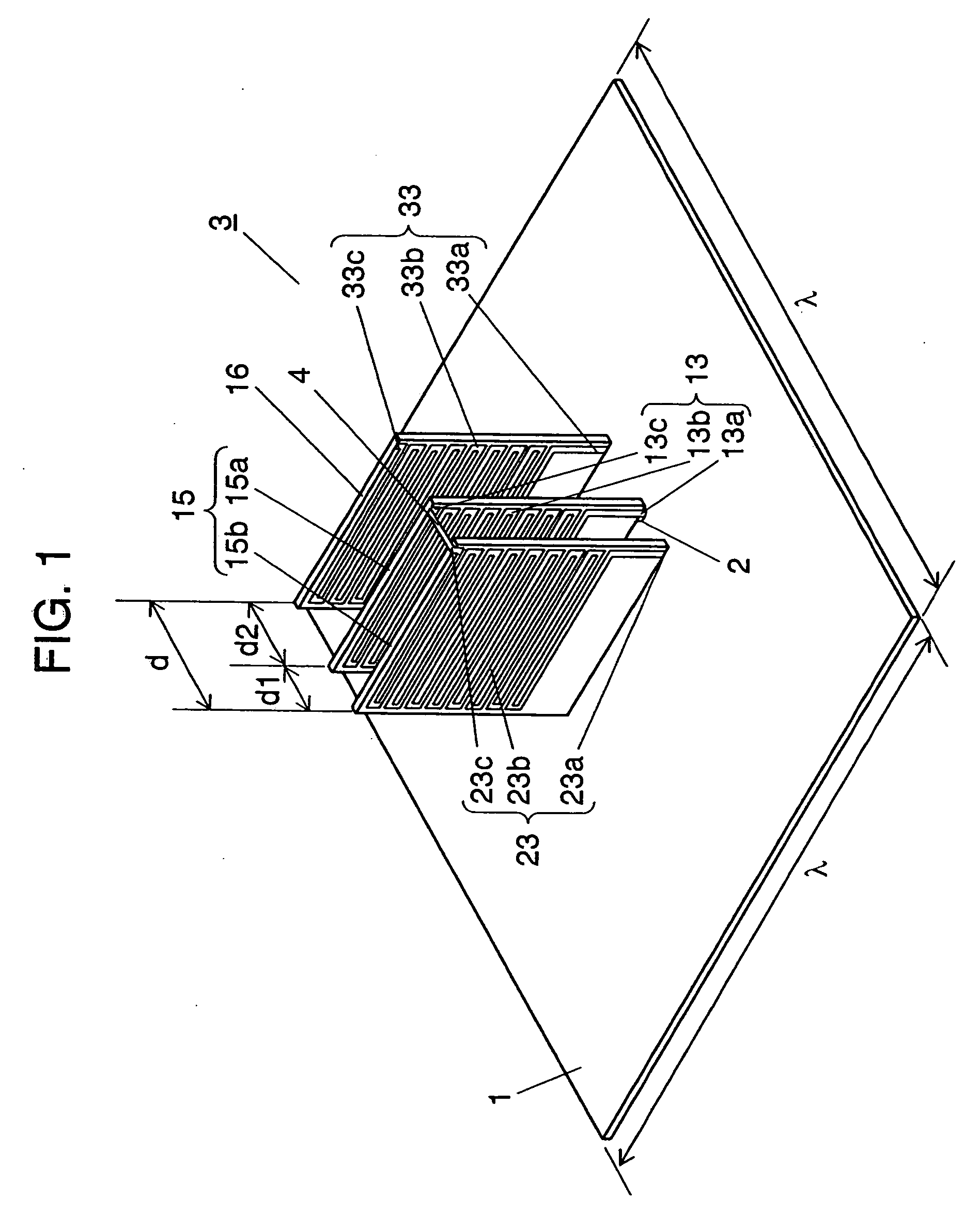
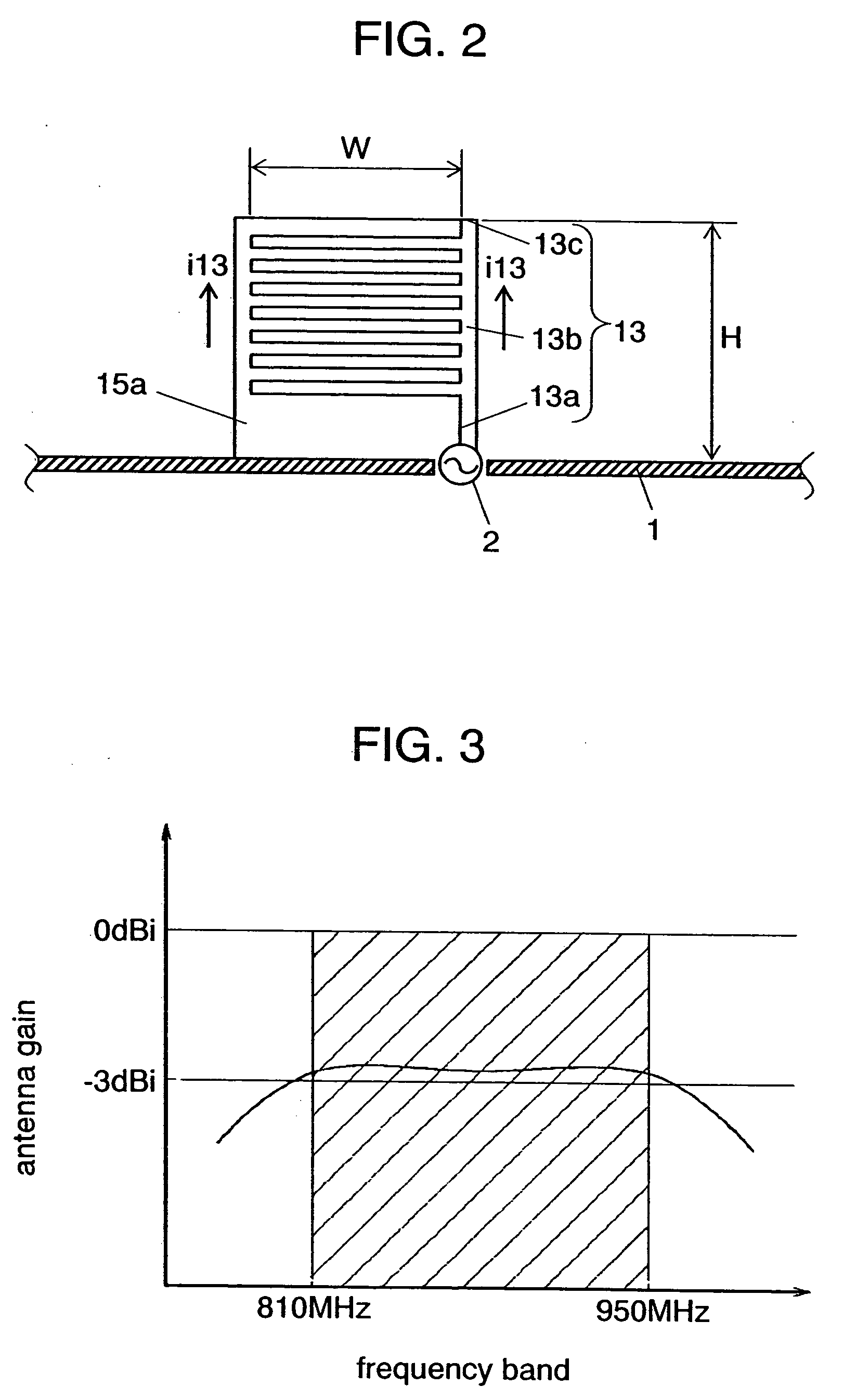
[0025] Exemplary embodiments of the present invention are demonstrated hereinafter with reference to FIG. 1-FIG. 5. FIGS. 1 and 2 are schematic diagrams illustrating an antenna in accordance with an exemplary embodiment of the present invention. FIG. 3 shows characteristics of an antenna in accordance with an exemplary embodiment of the present invention.

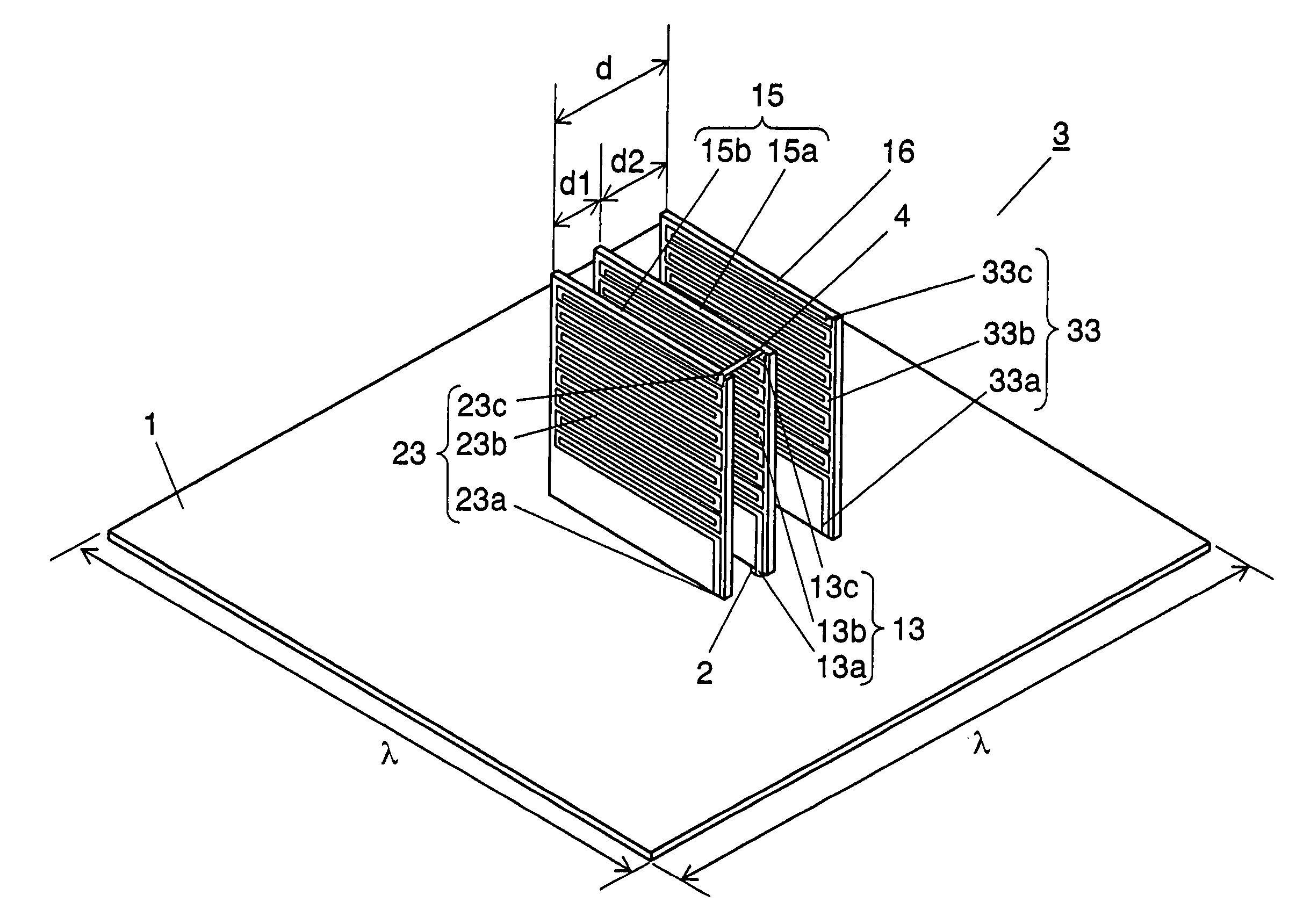
[0026] Antenna 3 includes planar conductive ground plate 1 made of copper and having length and width longer than one wavelength of its operating frequency. Antenna 3 also includes power feed point 2 at an approx. center of ground plate 1 for feeding high-frequency signals.

[0027] On the top surface of ground plate 1, first holder 15a, second holder 15b and support 16 stand approx. upright and confront each other at intervals “d1” and “d2” in between. In the exemplary embodiment, d1=2 (mm) and d2=4 (mm) are selected respectively. However, this invention is not limited to the set of values.

[0028] Holders 15a, 15b and support 16 are...


PUM


Abstract

On the top surface of conductive ground plate, first holder having first antenna element, second holder having second antenna element, and support having parasitic antenna element are provided such that holders and support confront each other. Respective intermediate sections of antenna elements are folded to shape like “square C” in plural times, so that antenna is formed. The foregoing construction allows low-profiling and downsizing antennas to be used in mobile radio devices.

Description

FIELD OF THE INVENTION [0001] The present invention relates to antennas such as mobile antennas to be used in mobile radio devices. BACKGROUND OF THE INVENTION [0002] Recently, linear mono-pole antennas or folded mono-pole antennas have been used, in general, as mobile antennas for mobile radio devices. Those conventional antennas are described hereinafter with reference to FIGS. 6A and 6B. A conventional mono-pole antenna shown in FIG. 6A comprises planar conductive ground plate (or grand plane) 91 made of copper, power feed point placed at the center of ground plate 91, and antenna element 93 shaped like a wire or a rod and made of copper. Element 93 has a height of “H” in a vertical direction with respect to ground plate 91, and its first end P1 is coupled to power feed point while its second end P2 is open. [0003]FIG. 6B shows a conventional folded mono-pole antenna 100, which includes antenna element 103 shaped like “square C” formed by double-backing a copper wire or a copper ...

Claims


Application Information

Patent Timeline
Patent Type & Authority Applications(United States)
IPC IPC(8): H01Q1/24H01Q1/36H01Q9/30H01Q9/42
CPCH01Q1/242H01Q9/42H01Q1/362
Inventor FUJIKAWA, KAZUHIKOINATSUGU, SUSUMU
Owner PANASONIC CORP
Why Eureka
Try Eureka