Graphic image to 3D image conversion device

a conversion device and 3d image technology, applied in the field ofgraphic image to 3d image conversion device, can solve the problem that the 3d effect achieves only half of the effect, and achieve the effect of reducing color and improving entertainmen

Inactive Publication Date: 2005-12-22
CHEN CHUAN SHENG
View PDF21 Cites 20 Cited by
  • Summary
  • Abstract
  • Description
  • Claims
  • Application Information

AI Technical Summary

Benefits of technology

[0007] The primary purpose of the present invention is to provide a device to convert graphic into 3D image. To achieve the purpose, time lapse is created through special electronic principles from the time of creating current using physical principles. Again physical principles are incorporated to produce the phenomenon of horizontal translation. Both eyes of a viewer receive the images and those images are incorporated in the brain of the viewer to create 3D effect. The device is essentially comprised of image input loop, image control loop, image output of parity horizontal translation IR circuit, and IR spectacles to receive image. Wherein, image input separate the image and color through image input loop, the image is then divided into odd field and even field images through image control loop. Time lapse controller is used to defer odd or even filed image for the image to be integrated by controller of horizontal translation loop to create image and deliver the image to digital detec

Problems solved by technology

However, such a 3D effect actually achieves only half of the effect by failing to completely pre

Method used


Image

  • Graphic image to 3D image conversion device
  • Graphic image to 3D image conversion device
  • Graphic image to 3D image conversion device

Examples


Embodiment Construction

[0013] The following descriptions are of exemplary embodiments only, and are not intended to limit the scope, applicability or configuration of the invention in any way. Rather, the following description provides a convenient illustration for implementing exemplary embodiments of the invention. Various changes to the described embodiments may be made in the function and arrangement of the elements described without departing from the scope of the invention as set forth in the appended claims.

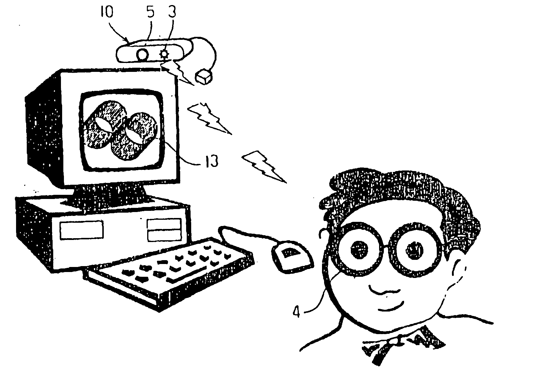
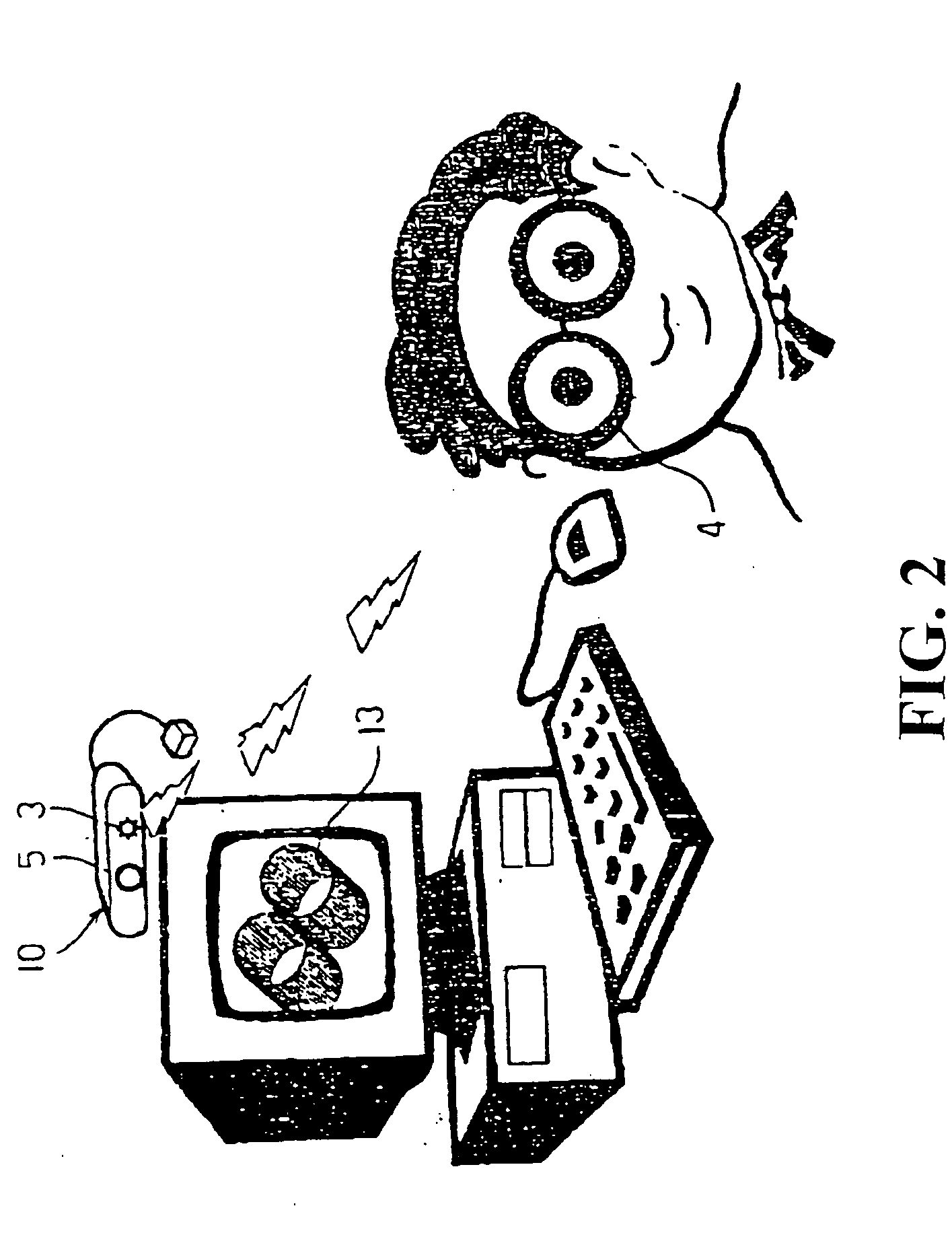
[0014] Referring to FIGS. 2 and 3, a preferred embodiment of the present invention is essentially comprised of an image input loop 1, an image control loop 2, an output parity horizontal translation image IR circuit 3, and a pair of IR spectacles 4. After the process by a wave-shaping circuit 11, the image is transmitted to a divider 12 under the control of the image input loop 1 to be separated into an odd image 21 and an even image 22. The image after the separated is transmitted to a phase d...


PUM


Abstract

A device applicable to computers, TV sets, and projectors for converting a graphic image into a 3D image includes an image input loop, image control loop, output parity horizontal translation image IR circuit, and IR spectacles, wherein the IR spectacles create masking effect on both eyes, a CF lens is used to receive images of horizontal translation in conjunction with personal persistence of vision, and images are combined in the viewer's brain to present a 3D image.

Description

BACKGROUND OF THE INVENTION [0001] (a) Technical Field of the Invention [0002] The present invention is related to a device to convert a graphic image of a video game or film into two images in sequence of horizontal translation to display a 3D picture, and more particularly to one that works on physical principles incorporated with electronic technology to convert a graphic into a 3D picture, and the picture received by a pair of spectacles is transmitted to one's brain to view the 3D picture, or video game and image through personal persistence of vision. [0003] (b) Description of the Prior Art [0004] In the prior art, an RB polarizing filter is used to create 3D image by taking advantage of visual variance to produce 3D effects. Thanks to the rapid development of technology, the image is produced into a 3D image by a software application. Once the image is produced, the 3D effect is present to the viewer. However, such a 3D effect actually achieves only half of the effect by fail...

Claims


Application Information

Patent Timeline
IPC IPC(8): G06F17/00G06T1/00H04N13/00
CPCH04N13/0497H04N13/0438H04N13/341H04N13/398
Inventor CHEN, CHUAN-SHENG
Owner CHEN CHUAN SHENG
Why Eureka
Try Eureka