Rotary fluid agitator

a rotary fluid agitator and rotary technology, applied in the direction of mixing liquids with solids, mixing methods, mixers, etc., can solve the problems of requiring a worker to be stationed at each tank, solids settle to the bottom of the tank, and it is difficult to reintegra

Inactive Publication Date: 2005-12-22
YUNGBLUT JOHN DAVID
View PDF13 Cites 28 Cited by
  • Summary
  • Abstract
  • Description
  • Claims
  • Application Information

AI Technical Summary

Benefits of technology

[0010] In additional embodiments, several nozzles can be include to increase the action performed up

Problems solved by technology

However, there is a significant portion of the fluid in the tank that s not affected by the rotation of the blades, particularly long the perimeter of the tank and solids tend to settle and build up there.
However, it has the disadvantage of requiring a worker to be stationed at each tank to operate the gun.
As a result it is only practical to use this technique intermittently and as a result solids settle to the bottom of the tanks where they are difficult to reintegrate into the drilling fluid.
There are many deficiencies with the current preferred system.
First, is that the useful and valuable solids in the drilling fluid settle to the bottom of the tanks along with the formation cuttings and can not be picked up by the pump suction to be properly processed by the drilling fluid

Method used


Image

  • Rotary fluid agitator
  • Rotary fluid agitator
  • Rotary fluid agitator

Examples


Embodiment Construction

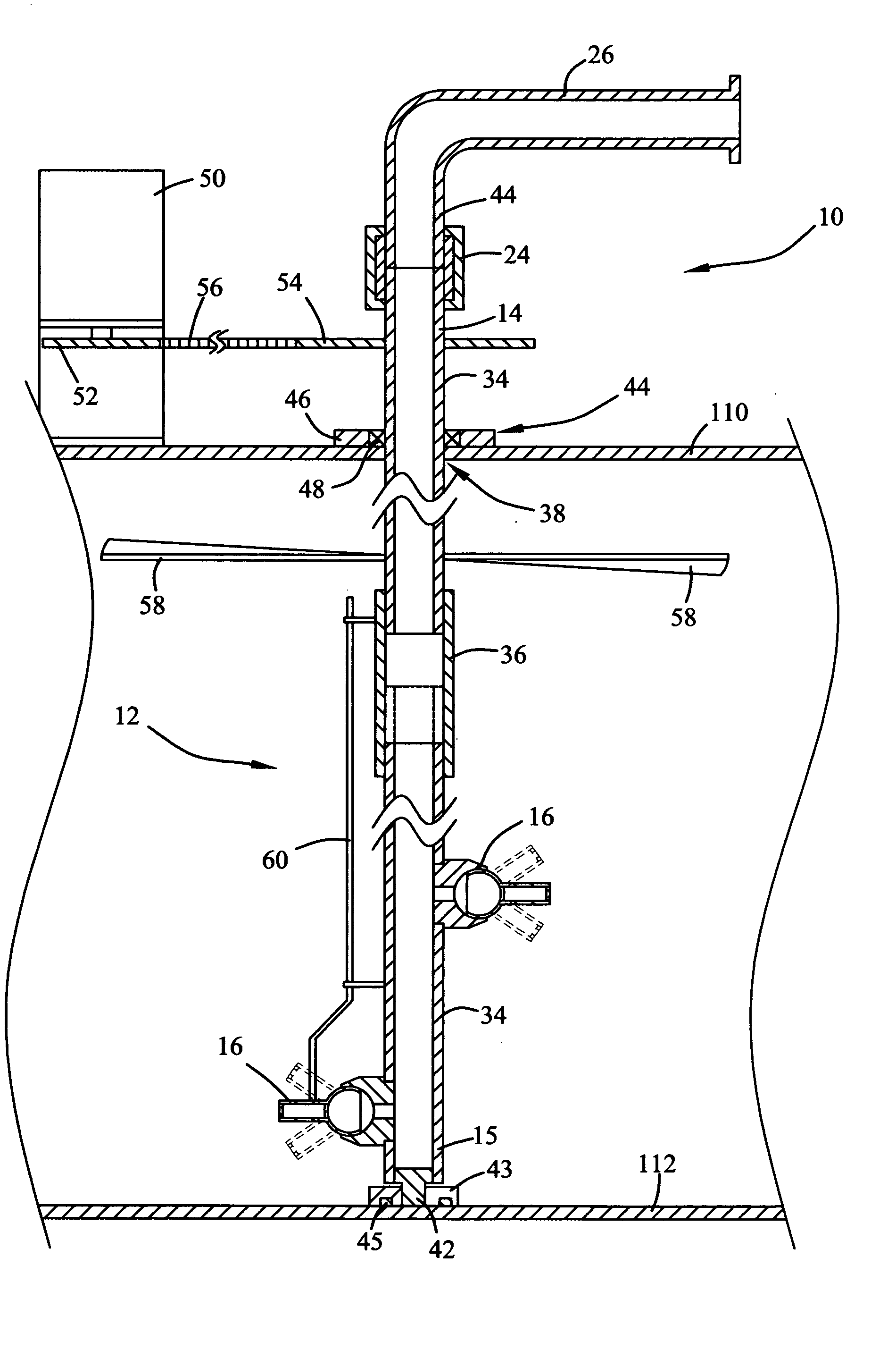
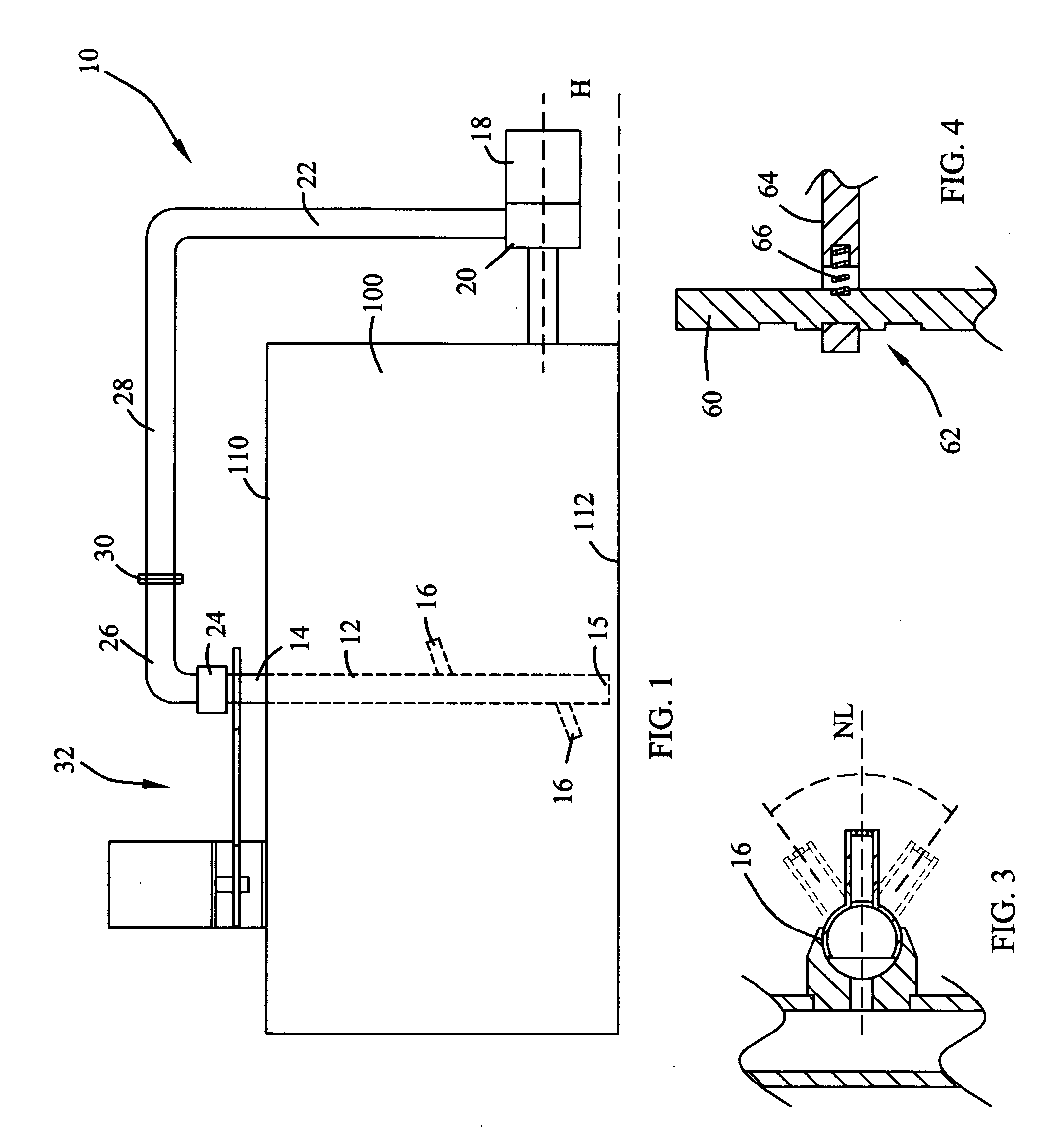
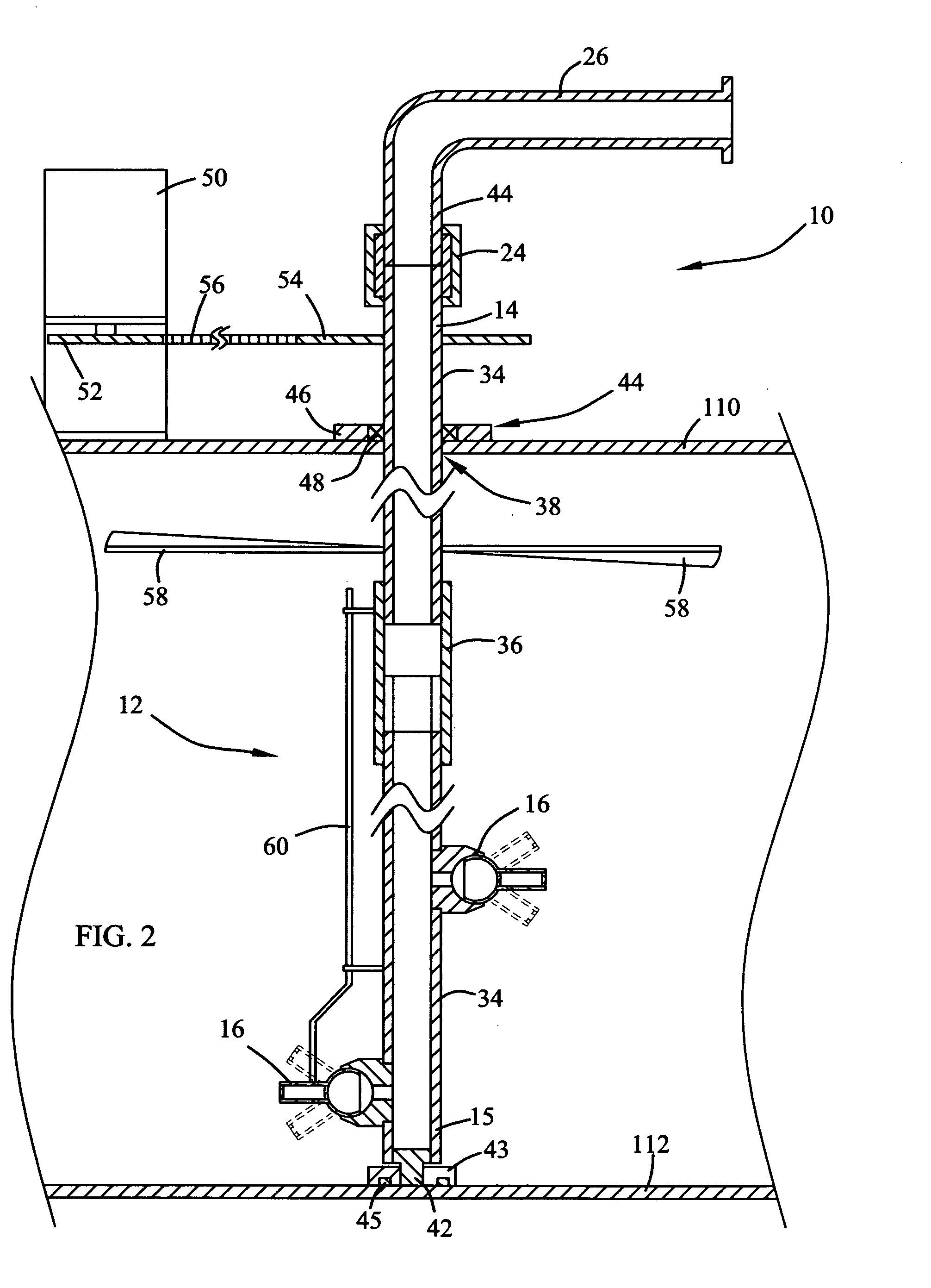
[0021] Referring now to the drawings, and particularly to FIGS. 1-3, a preferred embodiment of the rotary fluid agitator of the present invention is shown and generally designated by the reference numeral 10. It is important to note, the design of the rotary fluid agitator 10 is that so not only are solid particulates mixed with a fluid are maintained in suspension, but so that the number of elemental parts of the rotary fluid agitator which are placed in contact with the fluid is a minimum to reduce contamination to the fluid by the elemental parts. Additionally, the present invention is designed to reduce operation wear resulting from abrasion created by the suspended solids. This design will become apparent upon reading the remaining disclosure.

[0022] Reference is first made to FIG. 1 which schematically illustrates the rotary fluid agitator 10 and a fluid storage tank 100. The tank 100 is a typical tank used to contain fluids, such as drilling fluids and which has an interior v...


PUM

PropertyMeasurementUnit
Angleaaaaaaaaaa
Lengthaaaaaaaaaa
Volumeaaaaaaaaaa

Abstract

A rotary fluid agitator is provided. The rotary fluid agitator essentially comprises a fluid conduit that is positioned vertically within a storage tank holding a quantity of fluid, such as a drilling fluid. At least one nozzle is attached to the fluid conduit for jetting a stream of fluid into to the fluid contained within the tank. A drive means is connected to the fluid conduit and rotates the conduit to sweep the nozzle through a 360-degree arcuate path at a predetermined rotational frequency. A fluid pump is attached in fluid communication with the interior volume of the tank and pumps a quantity of drilling fluid through a fluid circulation line and through the fluid conduit to be jetted out of the nozzle. As the nozzle is swept through the arcuate path a conically shaped fluid flow path is created in the fluid contained within the tank causing the jetted fluid to tangentially act upon the fluid thereby keeping all solid particulates mixed with the fluid in suspension.

Description

BACKGROUND OF THE INVENTION [0001] 1. Field of the Invention [0002] The present invention relates generally to an improved means of mixing, stirring and maintaining solids in suspension in a liquid. More particularly, relating to an apparatus for maintaining in suspension a complex drilling fluid mixture during storage of the drilling fluid within a storage tank. [0003] 2. Background of the Invention [0004] In the operations carried out to drill a borehole through a formation a mixture of chemical, water or oil, and solids such as bentonite, barite and drilled formation particulates, referred to as “drilling fluid” or “drilling mud” is circulated down through a drill string, and through a drill bit where the mixture performs a number of important functions. Such functions include cooling the drill bit, lubricating the drill bit, flushing formation cuttings from the face of the drill bit and then transporting the formation cuttings up annulus between the drill string and the wall of ...

Claims


Application Information

Patent Timeline
IPC IPC(8): B01F3/12B01F5/02B01F5/04B01F5/10B01F13/08
CPCB01F3/12B01F5/104B01F5/10B01F5/0218B01F23/50B01F25/212B01F25/52B01F25/50
Inventor YUNGBLUT, JOHN DAVID
Owner YUNGBLUT JOHN DAVID
Why Eureka
Try Eureka