Abnormality determining apparatus, image forming apparatus including the abnormality determining apparatus, and abnormality determining method

a technology of abnormal density and determining apparatus, which is applied in the direction of digital output to print units, instruments, nuclear elements, etc., can solve the problems of inability to determine whether the density of output images is decreasing, and it is difficult to determine the presence of abnormalities, etc., to achieve accurate determination of the presence or absence of abnormalities

Inactive Publication Date: 2005-12-22
RICOH KK
View PDF21 Cites 56 Cited by
  • Summary
  • Abstract
  • Description
  • Claims
  • Application Information

AI Technical Summary

Benefits of technology

[0013] Therefore, as discovered by the present inventors, it is desirable to provide an abnormality determining apparatus that can accurately determine the presence or absence of abnormality in each d

Problems solved by technology

However, in various types of devices on the market, it may be difficult to determine the presence of an abnormality based on only one type of parameter, and it may be necessary to take an interrelation among a plurality of parameters into consideration to detect an abnormality.
Specifically, when solid images are continuously output while consuming a large amount of toner and a developing device cannot be replenished with a sufficient amount of toner, the decrease of density of an output image typically occurs even if the apparatus has no abnormality.
In this case, it cannot be determined whether such a density decrease is caused by an abnormality of the apparatus based on only one parameter such as density of an output image.
However, the following problems still need to be addressed.
The first problem is that an operation for constructing a normal group data set is complicated.
However

Method used


Image

  • Abnormality determining apparatus, image forming apparatus including the abnormality determining apparatus, and abnormality determining method
  • Abnormality determining apparatus, image forming apparatus including the abnormality determining apparatus, and abnormality determining method
  • Abnormality determining apparatus, image forming apparatus including the abnormality determining apparatus, and abnormality determining method

Examples


Embodiment Construction

[0041] Example of embodiments of the present invention are described with reference to the drawings, wherein like reference numerals designate identical or corresponding parts throughout the views.

[0042] First, an example of an image forming apparatus acting as a detection subject of an abnormality determining apparatus is described. The image forming apparatus may be, for example, a copying machine, a printer, a facsimile, or other similar image forming apparatuses.

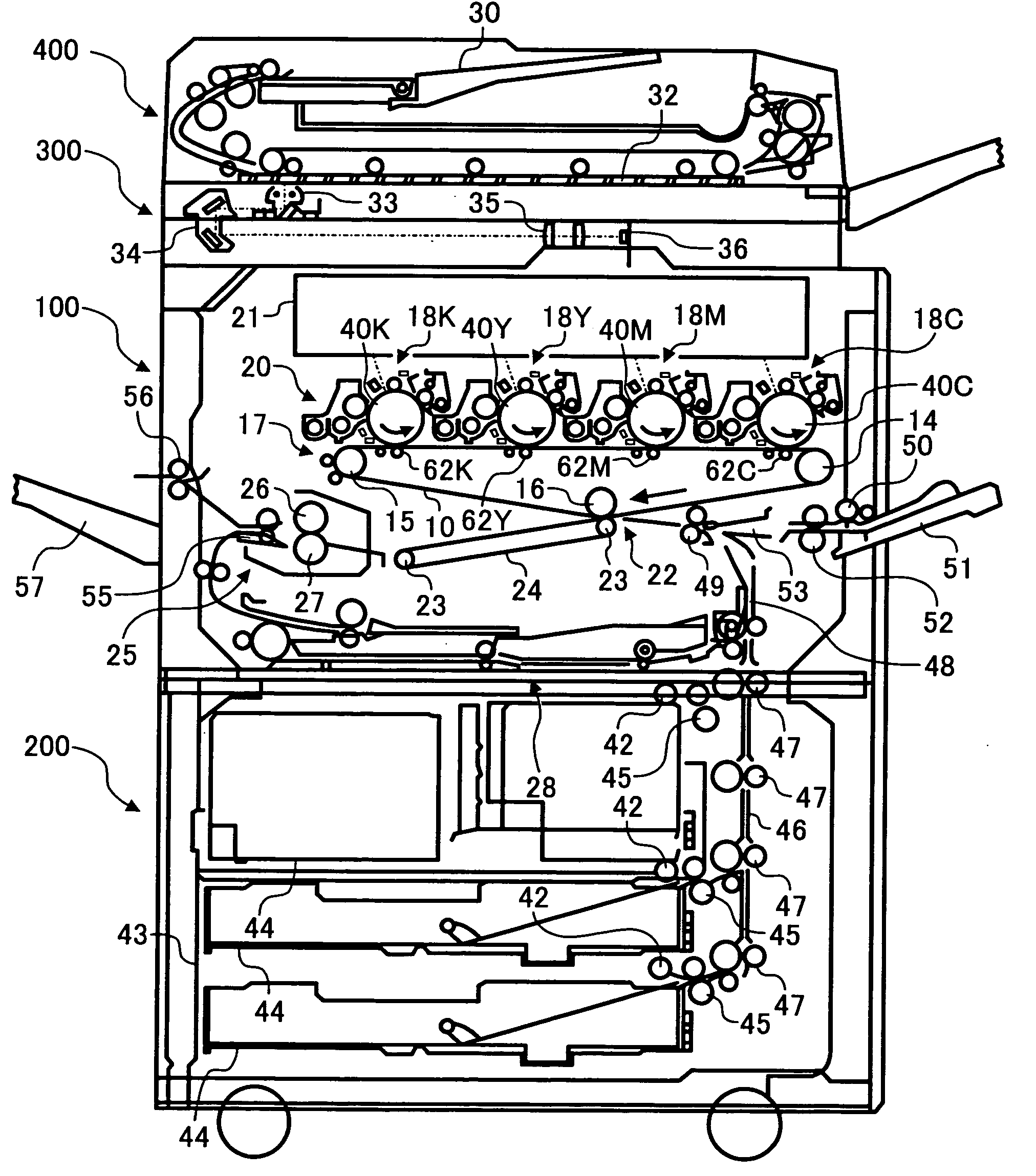
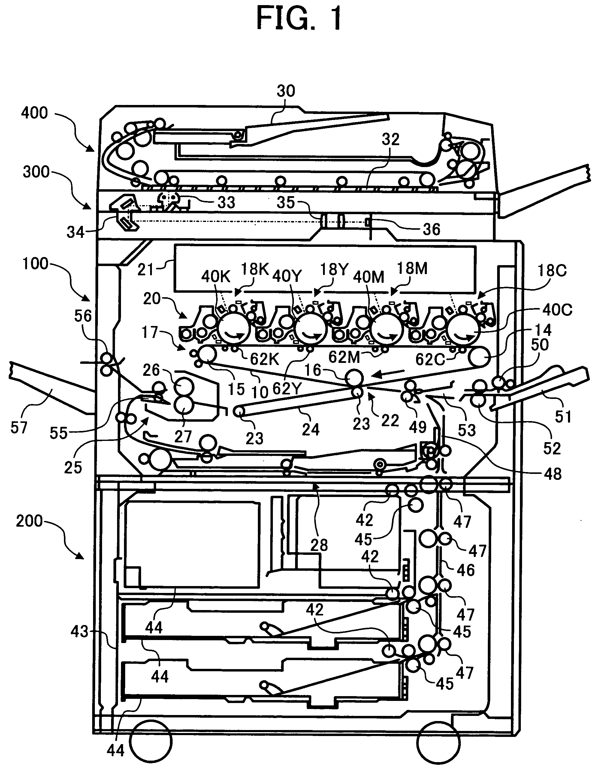
[0043]FIG. 1 is a schematic cross section of an image forming apparatus used as a detection subject of an abnormality determining apparatus according to an embodiment of the present invention. The image forming apparatus includes an image forming device having a printer unit 100, a sheet feeding unit 200, a scanner unit 300, and an automatic document feeder (ADF) 400. The scanner unit 300 is attached to the top of the printer unit 100. The ADF 400 is attached to the top of the scanner unit 300.

[0044] The scanner unit ...


PUM


Abstract

An abnormality determining apparatus includes an information storing device that stores information, an information obtaining device that obtains information of a detection subject, a receiving device that receives abnormality presence/absence information indicative of the presence or absence of an abnormality in the detection subject detected by a user, a normal group data set constructing device that constructs a normal group data set that is a collection of normal data indicating that the detection subject is in a normal state based on the abnormality presence/absence information received by the receiving device and based on the information obtained by the information obtaining device during a preset period, and a determining device that determines the presence or absence of an abnormality in the detection subject by performing calculations based on the normal group data set stored in the information storing device and based on the information obtained by the information obtaining device.

Description

CROSS-REFERENCE TO RELATED APPLICATIONS [0001] This application claims priority to Japanese Patent Application No. 2004-183031 filed in the Japanese Patent Office on Jun. 21, 2004, the entire contents of which is hereby incorporated by reference herein. BACKGROUND OF THE INVENTION [0002] 1. Field of the Invention [0003] The present invention relates to an abnormality determining apparatus and an abnormality determining method for determining the presence or absence of an abnormality in a detection subject based on a result obtained by an information obtaining device that obtains information of the detection subject. [0004] 2. Discussion of the Background [0005] An abnormality determining apparatus that determines the presence or absence of an abnormality in a detection subject has been used. For example, a thermal test device used in an electric control circuit is an example of an abnormality determining apparatus that determines an abnormality in an electronic product acting as a d...

Claims


Application Information

Patent Timeline
IPC IPC(8): G03G15/00G03G21/00G06F15/00
CPCG03G15/55G03G2215/00059G03G15/5079G03G15/5054G03G15/556G03G15/0131
Inventor NAKAGAWA, YOSHINORISHOJI, HISASHINAKAZATO, YASUSHIOUCHI, SATOSHIMATSUURA, NEKKASATOH, OSAMUHIRAI, SHUJIHOSHINO, SEIJIMIYAWAKI, KATSUAKI
Owner RICOH KK
Why Eureka
Try Eureka