Seal component for use with a spherical rod end assembly

a technology of spherical rod end assembly and seal component, which is applied in the direction of threaded fasteners, screw heads, couplings, etc., can solve the problems of excessive wear of components, poor performance, and exacerbate such problems, and achieve the effect of improving seal integrity and high angularity

Inactive Publication Date: 2005-12-22
SEALS IT
View PDF32 Cites 15 Cited by
  • Summary
  • Abstract
  • Description
  • Claims
  • Application Information

AI Technical Summary

Benefits of technology

[0006] The above discussed and other drawbacks and deficiencies of the prior art are overcome or alleviated by the provision of an assembly comprised of a spherical rod end having a head portion with an opening of spheric cross section therewithin, a ball pivotably seated within the opening of the head portion, and fastener means is presented. A first component of the fastener means has a shank portion extending through a bore in the ball, and a second component thereof is engaged on the shank portion of the first. One component (be it the “first” or “second”, or a “third” component) of the fastener means, disposed on each side of the rod end portion, constitutes a seal component and is comprised of a rigid body element and a sealing element, the latter having an annular inner portion continuously surrounding the peripheral marginal portion of the body element and sealingly affixed to it. A flexible, resilient, composite wall portion extends from about the inner portion of the seal element and is outwardly flared to terminate at a flexible peripheral radiused lip, the lip being in movable sealing engagement with the exterior surface of the head portion to which it is adjacent, surrounding the opening therein. Seal integrity and high angularity is improved by a living hinge intermediate the wall portion and annular inner portion attached to the rigid body element. The wall portion of the sealing element is comprised of a shell made of a tough, dense, nonporous material.

Problems solved by technology

Unless effectively sealed, dirt and other foreign matter invariably collects within the ball-seating cavities of such assemblies, causing excessive wear of components and poor performance ineffective lubrication will of course exacerbate such problems.

Method used


Image

  • Seal component for use with a spherical rod end assembly
  • Seal component for use with a spherical rod end assembly
  • Seal component for use with a spherical rod end assembly

Examples


Embodiment Construction

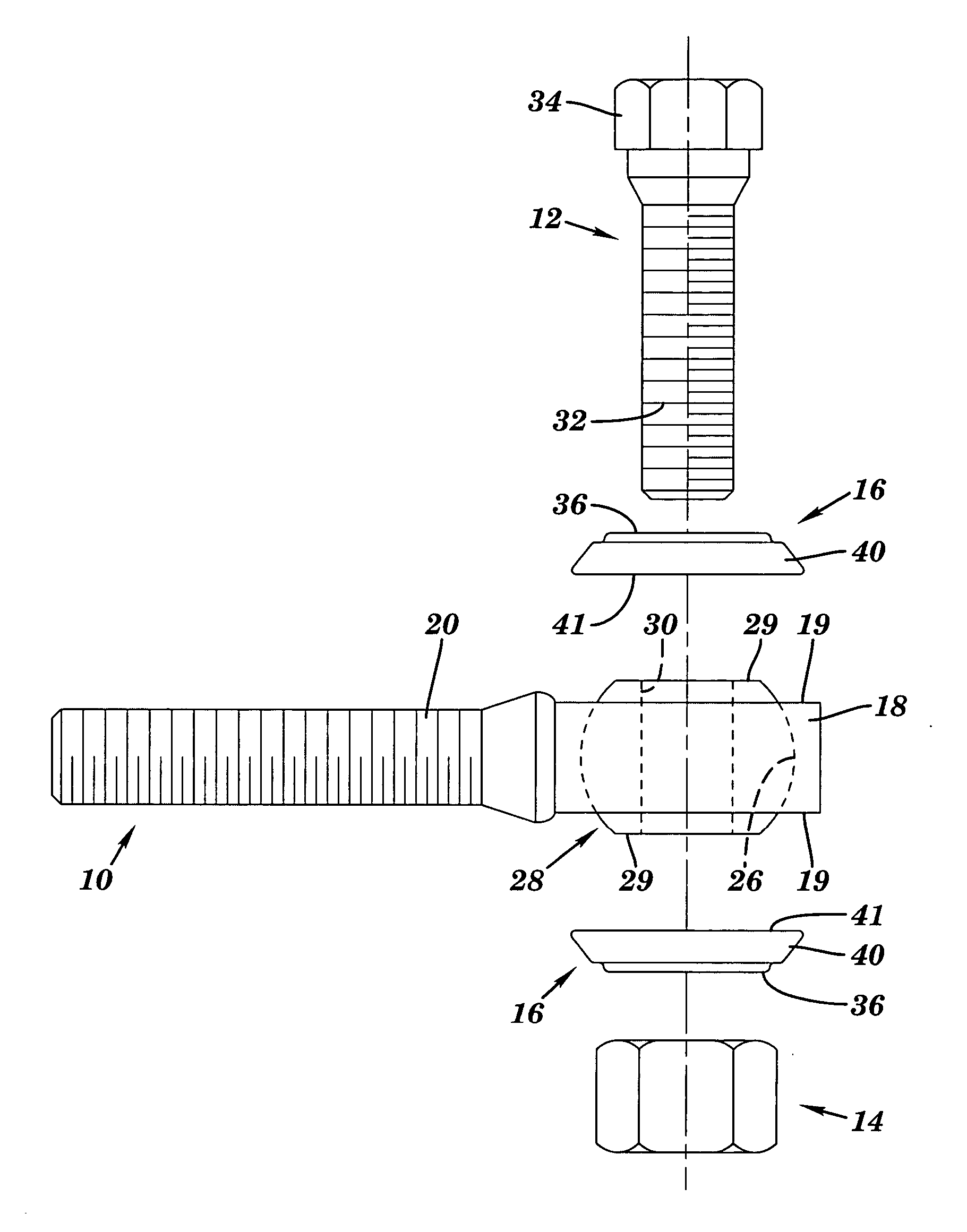
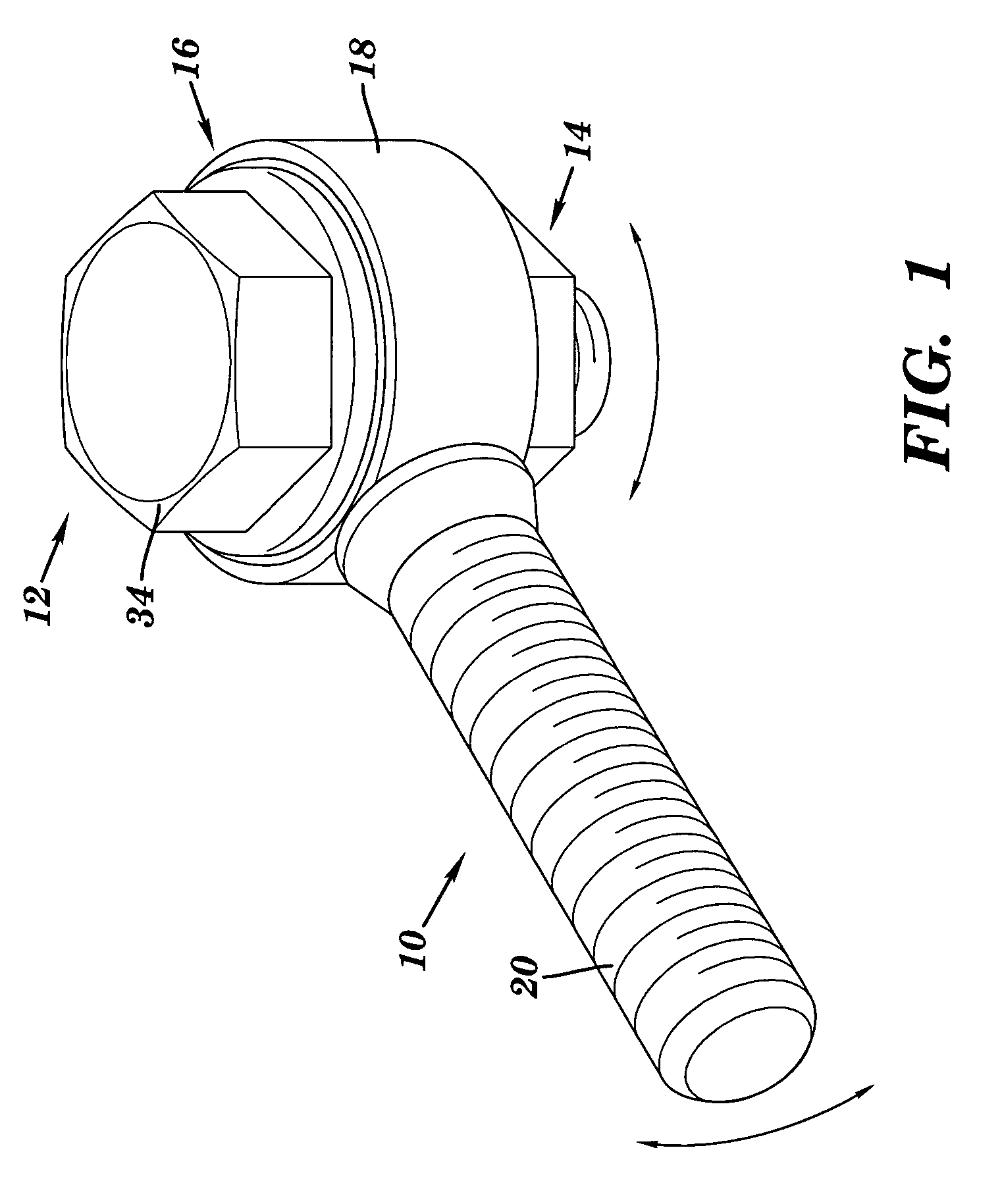
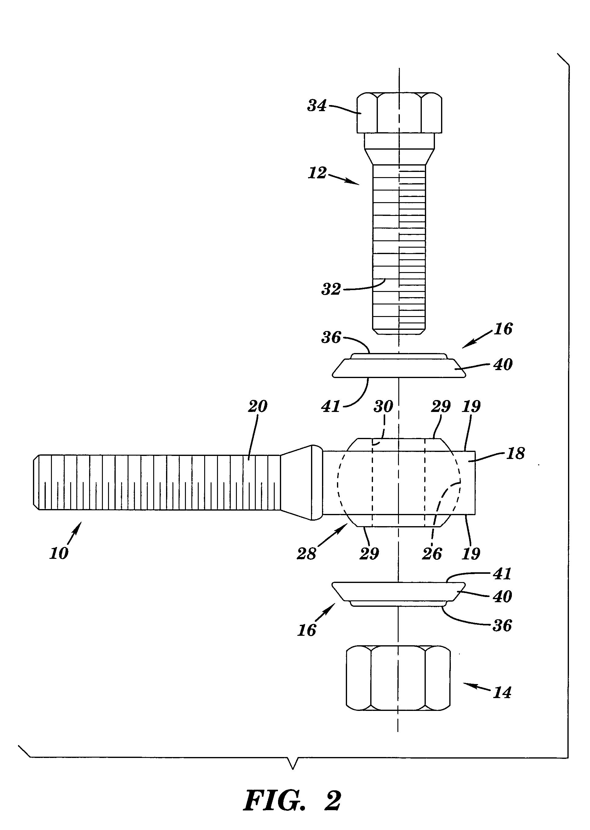
[0025] Turning first in detail to FIGS. 1-5 of the appended drawings, therein illustrated is a spherical rod end assembly embodying the present invention, including a spherical rod end, a bolt, a nut and a pair of sealing washers, generally designated respectively by the numerals 10, 12, 14 and 16. The rod end 10 consists of a head portion 18 and a threaded shank portion 20, the head portion 18 having an integral insert 24 (FIG. 5) affixed thereon, providing an opening 26 defined by a spheric wall surface. A truncated ball, generally designated by the numeral 28, is rotatably and pivotably seated within the opening 26, and has a diametric bore 30 through which extends the threaded shaft 32 of the bolt 12.

[0026] Each of the sealing washer components 16 consists of a metal washer 36 and a flared, frustoconical composite skirt element, generally designated by the numeral 40, Skirt element 40 includes a circumferential living hinge 100 therein defining an annular relief as best seen in...


PUM


Abstract

A spherical rod end assembly includes a seal component in the form of a fastener or a washer, or a combination thereof. The seal component has a flexible, resilient skirt, affixed to a metal body, which skirt overlies and seals the cavity within which the ball of the assembly is seated, to exclude dirt and other foreign matter, and to enhance lubrication. The seal component further includes a circumferential living hinge formed therein to improve seal integrity and increase angularity of the skirt.

Description

BACKGROUND OF INVENTION [0001] Spherical rod end assemblies are extensively used for a wide variety of applications, such as in steering linkages for land vehicles, in aircraft surface controls, in automatic door control mechanisms, and in numerous other mechanical, hydraulic and pneumatic systems. Unless effectively sealed, dirt and other foreign matter invariably collects within the ball-seating cavities of such assemblies, causing excessive wear of components and poor performance ineffective lubrication will of course exacerbate such problems. [0002] Elements made of rubbery materials have in the past been used in assembly with nuts, bolts and washers, to seal thread joints and to prevent loosening of engaged components. Disclosures of that kind are found in the following U.S. patents including: Hultgren et al., U.S. Pat. No. 1,567,649, Wagner U.S. Pat. No. 3,519,279, Onufer U.S. Pat. No. 3,572,414, Brown U.S. Pat. No. 3,585,894, Dahl U.S. Pat. No. 3,803,793, and DeHaitre U.S. Pa...

Claims


Application Information

Patent Timeline
Patent Type & Authority Applications(United States)
IPC IPC(8): F16B35/06F16C11/06F16D1/12
CPCF16B35/06F16C11/0614Y10T403/32631F16C11/0666F16C23/045F16C33/74F16C11/0676
Inventor MATCZAK, STANLEY E.
Owner SEALS IT
Why Eureka
Try Eureka