Method and apparatus for igniting a gas flare and a gas flare

a technology of gas flares and igniting devices, which is applied in the direction of combustion ignition, lighting and heating devices, combustion processes, etc., can solve the problem that most forms of igniters have an unexceptably short life span

Inactive Publication Date: 2005-12-22
RASMUSSEN ADAIR
View PDF5 Cites 1 Cited by
  • Summary
  • Abstract
  • Description
  • Claims
  • Application Information

AI Technical Summary

Benefits of technology

[0005] What is required is a more robust form of igniter which can function for relatively long time periods in an environment of extreme heat.

Problems solved by technology

A problem being encountered is that most forms of igniters have an unexceptably short life span when placed in an environment in the temperature range of 2000 to 2800 degrees fahrenheit.

Method used


Image

  • Method and apparatus for igniting a gas flare and a gas flare
  • Method and apparatus for igniting a gas flare and a gas flare
  • Method and apparatus for igniting a gas flare and a gas flare

Examples


Embodiment Construction

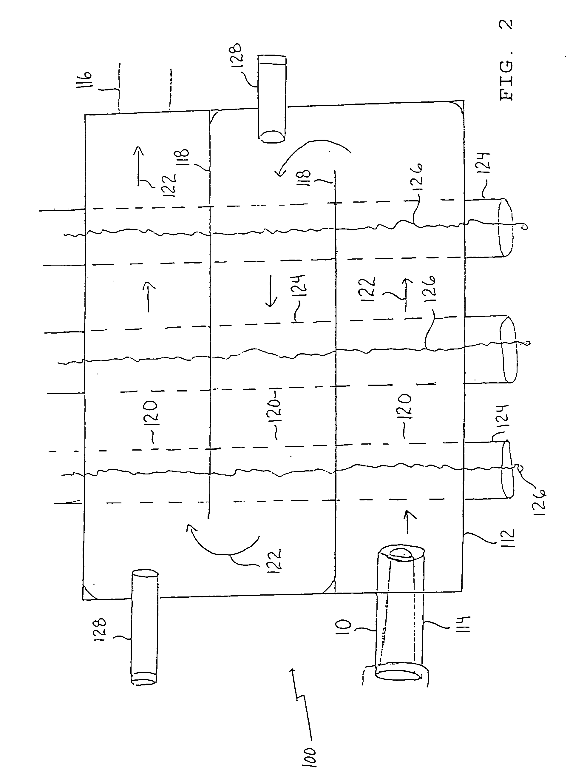
[0015] The preferred method will now be described with reference to an apparatus for igniting a gas flare, generally identified by reference numeral 10 and illustrated in FIG. 1 and a gas flare generally identified by reference numeral 100 and illustrated in FIG. 2.

[0016] Structure and Relationship of Parts for Apparatus 10:

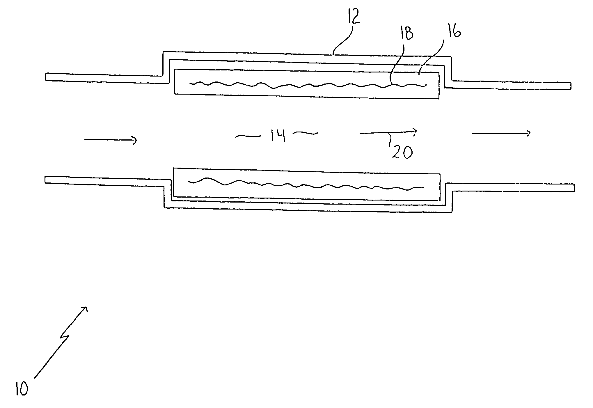
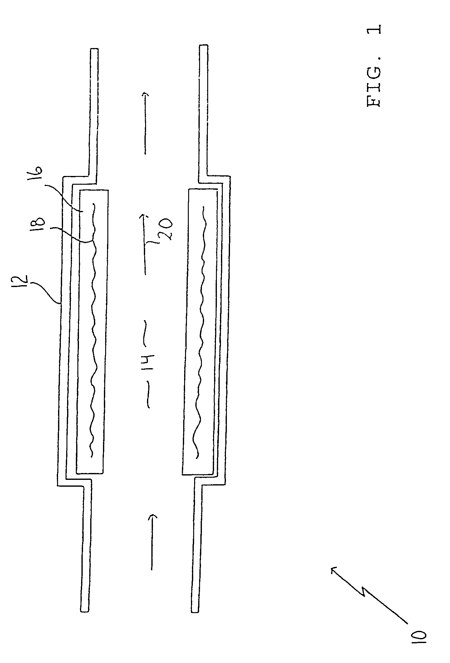
[0017] Referring to FIG. 1, igniter apparatus 10 includes a cylindrical housing 12. A flow passage 14 extends through housing 12. An annular ceramic body 16 lines flow passage 14. A heating element 18 imbedded in ceramic body 16 serves to maintain ceramic body 16 at a temperature above an ignition temperature of a combustible mixture of combustion air and combustible gases.

[0018] Operation:

[0019] The use and operation of igniter apparatus 10 will now be described with reference to FIG. 1. Igniter apparatus 10 is suitable for use where it is necessary to have a form of igniter which can function for relatively long time periods in an environment of extreme hea...


PUM


Abstract

A method and apparatus for igniting a gas flare includes a housing (12, 112) and at least one flow passage (14, 120) extending through the housing (12, 112). A body (16, 124) made from a heat conducting material in communication with the at least one flow passage (14, 120). A heating element (18, 126) embedded in the body (16, 124) maintains the body (16, 124) at a temperature above an ignition temperature of a combustible mixture of combustion air and combustible gases. The combustible mixture passing along the at least one flow passage (14, 120) is ignited immediately upon coming in contact with the body (16, 124). The apparatus can be a separate from the gas flare or can be incorporated into the construction of the gas flare.

Description

FIELD OF THE INVENTION [0001] The present invention relates to a method and an apparatus for igniting a gas flare and a gas flare equipped with the apparatus. BACKGROUND OF THE INVENTION [0002] Gas flares are used to burn combustible waste gases. Every gas flare has a pilot light or some other form of igniter to ensure that the gas flare does not go out, resulting in the waste gases being vented directly into the atmosphere. This is particularly important with hydrogen sulfide gas which is potentially lethal to human and animal life in relatively low concentrations. [0003] An increase in environmental awareness has lead to the monitoring of emissions from gas flares. It has been determined that if the waste gases are not burned at sufficiently high temperatures, noxious byproducts can be found in the emissions from the gas flares. The waste gas are, therefore, being burned at temperatures in a range of 2000 to 2800 degrees fahrenheit, in order to obtain a “clean” burn. [0004] A prob...

Claims


Application Information

Patent Timeline
Patent Type & Authority Applications(United States)
IPC IPC(8): F23G7/08F23Q7/10
CPCF23D2207/00F23Q7/10F23G7/08
Inventor RASMUSSEN, ADAIR
Owner RASMUSSEN ADAIR
Why Eureka
Try Eureka