Vacuum system for immersion photolithography

a vacuum system and photolithography technology, applied in the field of vacuum systems, can solve the problems of generating undesirable pressure and flow fluctuations, errors in the photolithography process, and general undesirable techniques, and achieve the effect of reducing the transmission of vibrations

Inactive Publication Date: 2005-12-22
ASML NETHERLANDS BV
View PDF12 Cites 92 Cited by
  • Summary
  • Abstract
  • Description
  • Claims
  • Application Information

AI Technical Summary

Benefits of technology

The invention uses flexible tubes to transfer fluids between different parts of a system without causing any harmful vibrations that could affect the quality of the fluid. These flexible tubes help separate out multiple phases of fluid and deliver them to their intended destinations with minimal loss of energy.

Problems solved by technology

The technical problem addressed in this patent is how to create a vacuum system that can remove a mixed phase fluid without causing pressure fluctuations that affect the quality of the photolithography process.

Method used


Image

  • Vacuum system for immersion photolithography
  • Vacuum system for immersion photolithography
  • Vacuum system for immersion photolithography

Examples


Embodiment Construction

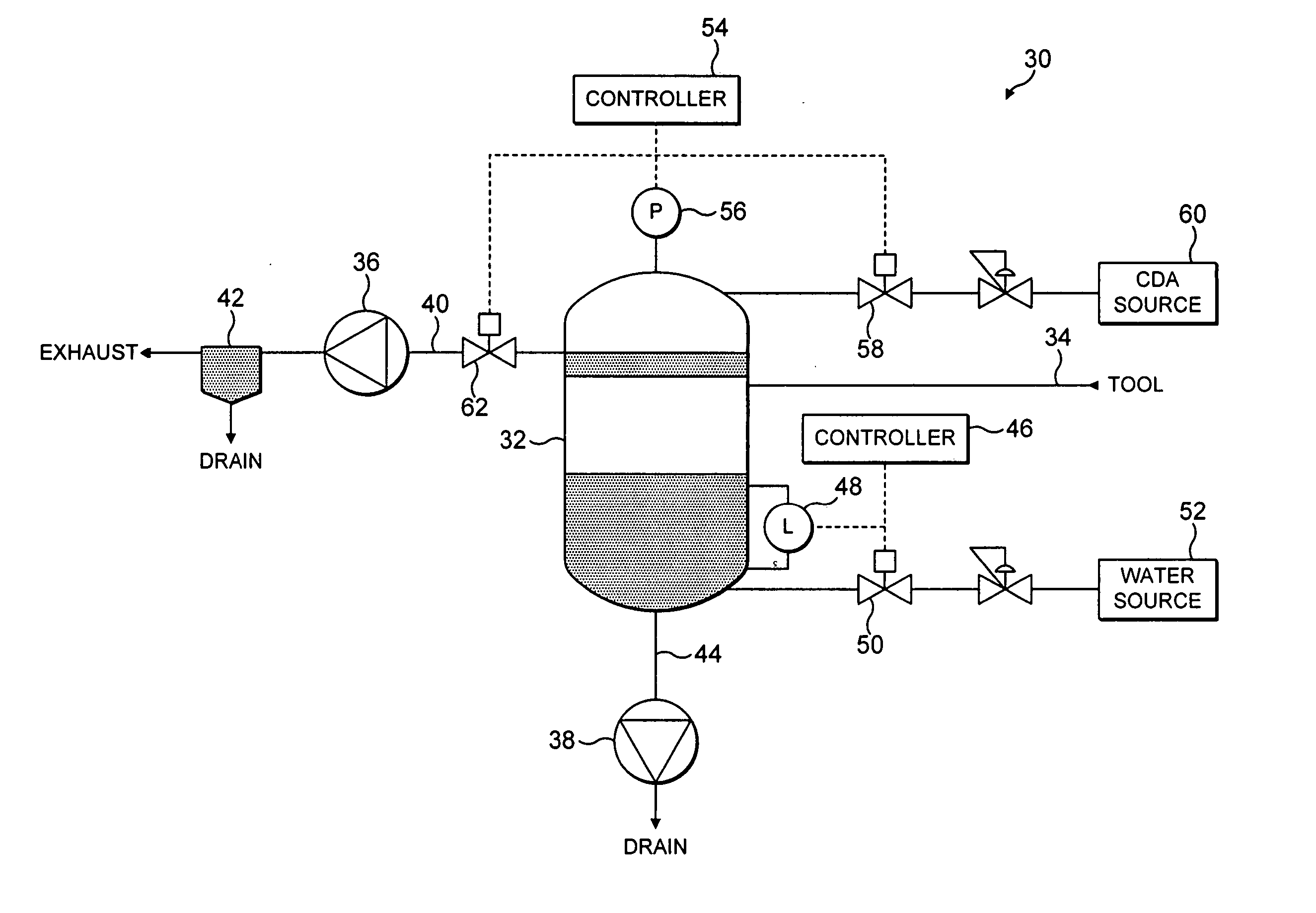
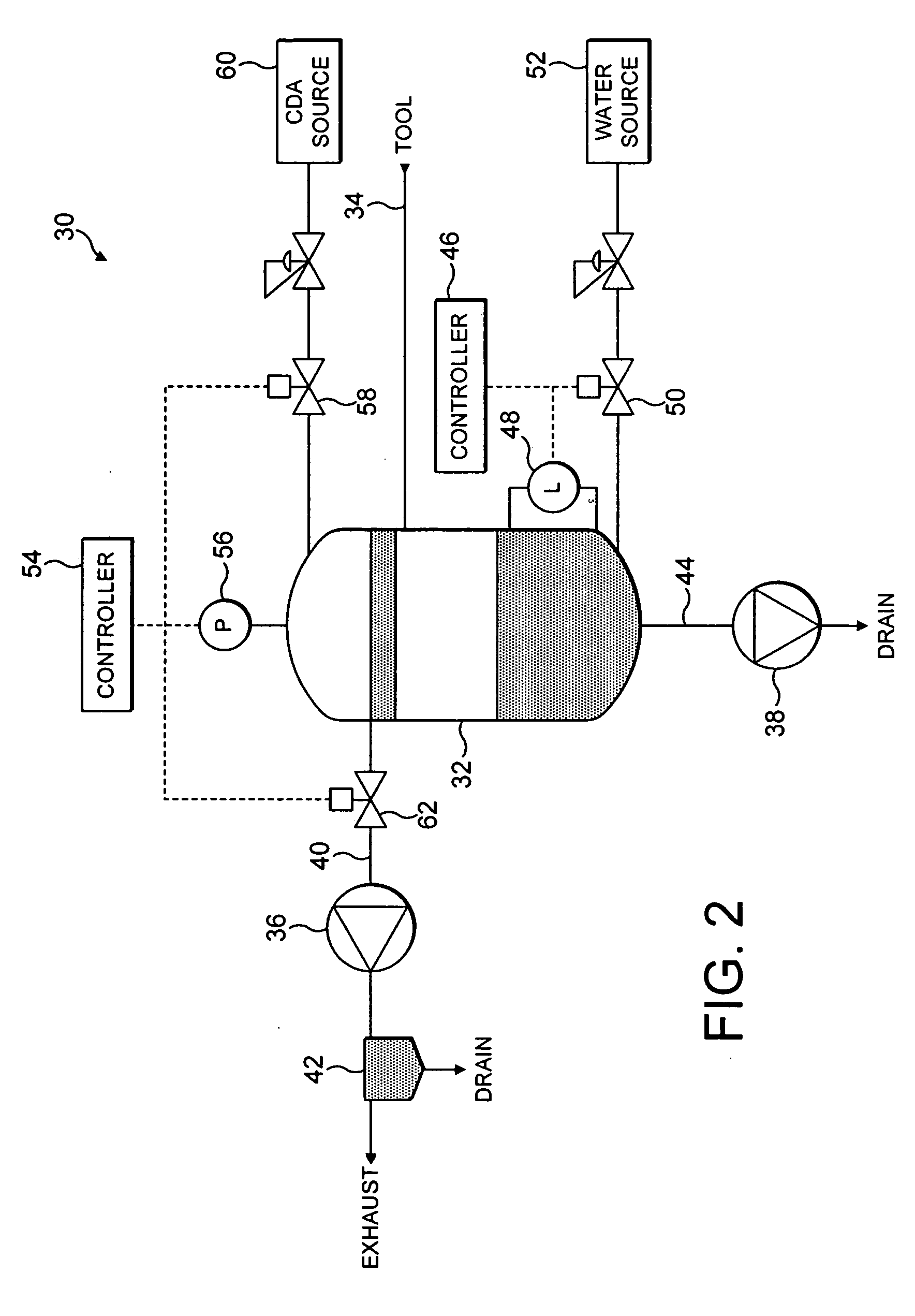
[0020] With reference to FIG. 2, a system 30 for extracting a multi-phase fluid from an immersion photolithography tool comprises a separating means depicted for purposes of illustration as an extraction tank 32 for receiving the multi-stream fluid drawn from the tool by a pumping arrangement located downstream from the tank 32. The tank 32 is connected to the tool by flexible tubing 34 so as to minimize the amount of mechanical coupling between the system 30 and the tool, and thereby minimize the transmission of vibrations generated during use of the system 30 back to the tool.

[0021] The tank 32 is configured to separate the liquid and gas phases within the fluid received from the tool. In this example, the fluid received from the tool comprises a mixture of clean dry air (CDA) and ultra-pure water, and so the tank 32 contains any suitable material and / or structure for affecting the separation of the CDA from the water. However, the tank 32 may be configured to separate a differen...


PUM

PropertyMeasurementUnit
Pressureaaaaaaaaaa
Flow rateaaaaaaaaaa
Flexibilityaaaaaaaaaa

Abstract

A vacuum system for extracting a stream of a multi-phase fluid from a photolithography tool comprises a pumping arrangement for drawing the fluid from the tool, and an extraction tank located upstream from the pumping arrangement for separating the fluid drawn from the tool into gas and liquid phases. The pumping arrangement comprises a first pump for extracting gas from the tank, and a second pump for extracting liquid from the tank. In order to minimize any pressure fluctuations transmitted from the vacuum system back to the fluid within the tool, a pressure control system maintains a substantially constant pressure in the tank by regulating the amounts of liquid and gas within the tank.

Description


Claims


Application Information

Patent Timeline
Owner ASML NETHERLANDS BV
Why Eureka
Try Eureka