Building reinforcing method, material and structure

a technology for reinforcing methods and structures, applied in the direction of building repairs, snow traps, transportation and packaging, etc., can solve the problems of reducing the internal space of the structure, and affecting the safety of workers

Inactive Publication Date: 2005-12-29
IGARASHI SHUNICHI
View PDF30 Cites 3 Cited by
  • Summary
  • Abstract
  • Description
  • Claims
  • Application Information

AI Technical Summary

Benefits of technology

[0016] To achieve the above objects, the present invention is configurationally characterized by utilizing the phenomenon that materials, such as concrete, wood, soil, and brick, which partially constitute various members, including structural members, expand in apparent volume upon rupture. Specifically, expansion of apparent volume is elastically confined by means of high-ductility materials (high-ductility covering materials) disposed around corresponding members including structural members, thereby delaying the progress of rupture and, after termination of imposition of an abrupt external force, thereby enabling the members to share with one another the weight of a structure and to substantially maintain their shapes. An apparent volume appearing herein refers to a volume enclosed by a surface (an enveloping surface) that smoothly envelopes the end and side faces of a member. Expansion of apparent volume resulting from rupture refers to the following phenomenon. As shown in FIG. 23(a), before rupture, a member 15 includes two end faces 2 and a side face 3. As shown in FIG. 23(b), the member 15 is ruptured along a rupture plane 4 into two rupture pieces 9. As a result of slide between the rupture pieces 9, an enveloping surface 10 is expanded; i.e., the apparent volume is expanded. As shown in FIG. 23(b), a cavity t is present between the enveloping surface 10 and the ruptured member 15. The present invention is configurationally characterized in that the member 15 is covered by a high-ductility material (a high-ductility covering material) such that a weak layer (including the cavity t) is provided between the member 15 and the high-ductility material, thereby enabling the high-ductility material (the high-ductility covering material) to be deformed along the enveloping surface even after rupture of the member 15.
[0019] In the first and second inventions, the high-ductility material is preferably a fibrous or rubber sheet material (including a tape-like sheet material). In this case, the high-ductility material may be rolled on a core to thereby form a cored roll of high-ductility material (a third invention). In the third invention, a plurality of parting lines, which can be visually or tactilely discriminated from one another, are drawn on one side of the high-ductility material along the length direction of the high-ductility material. The parting lines enable equally dividing the width of the high-ductility material at any one of two or more different pitches, thereby facilitating discrimination in division on a work site and thus contributing to enhancement of work efficiency. In the first or second invention, in consideration of installation conditions and work restrictions in relation to a member to be covered, the high-ductility material can be disposed in such a manner as to surround the member or to be spirally wound or rolled on the member. Alternatively, the high-ductility material can be disposed through application of a rubber or resin viscous-material to the member by appropriate application means, such as spraying. In the first or second invention, the high-ductility material (high-ductility covering material) can be disposed such that a cavity or a weak layer is interposed between the high-ductility material (high-ductility covering material) and the member, thereby avoiding direct rupture of the high-ductility material (high-ductility covering material) by the member and thus enabling the high-ductility material (high-ductility covering material) to yield an elastic confining effect more reliably. As a result of interposition of the cavity or weak layer, the high-ductility material (high-ductility covering material) can elastically confine expansion of apparent volume of the member in a far more reliable manner while maintaining an enveloping surface against diversified rupture form of the member (in FIG. 23(b), the cavity t is present between the member 15 and the enveloping surface 10).

Problems solved by technology

An external force imposed abruptly by earthquake or the like, or deficiency in yield strength stemming from deterioration has repeatedly caused an abrupt collapse of a structure, resulting in damage to lives and property.
Component members of a structure are ruptured due to excessive load or deficiency in yield strength.
Resultant deterioration of stability of the overall fabric of the structure causes significant deformation to the shape of the structure, thereby causing a reduction in the internal space of the structure; i.e., structural collapse.
In many cases of collapse of a building, floors fall down in a heap, like a stack of pancakes, or collapse.
In many cases of collapse of an elevated bridge, bridge piers are ruptured, resulting in collapse of the bridge.
When an external force in excess of the assumed level is imposed on a member, the member is ruptured, resulting in a failure to ensure the overall stability of a structure.
Thus, in many cases, the conventional measures involve excessively high cost.
Hiring such skilled workers is difficult nowadays.
Accordingly, even when an existing structure is known to involve a great risk of collapse due to deterioration, or because the structure is designed according to old standard or has been damaged by an external force imposed abruptly by earthquake or the like, in many cases, reinforcement of the structure has been unfeasible, for economic and physical reasons.
In a certain case, after occurrence of disaster, such as earthquake, when an examiner(s) entered a damaged structure in order to tentatively evaluate the degree of collapse risk, an aftershock caused the structure to collapse, with the result that the examiner(s) were killed or injured.
In another case, when dwellers and users entered a structure which was judged safe in view of minor damage, an aftershock caused the structure to collapse, resulting in heavy casualties.
As shown in FIG. 22, reinforcement enhances strength and / or toughness; however, there is no guarantee that the member can bear an upper load after a toughness limit is exceeded.
However, in the case of deformation in excess of the range, a mechanism for bearing a load is lost, resulting in rapid progress of deformation.
As a result, collapse of the structure becomes unavoidable.
However, the shearing stress S causes a shear fracture of the column 1 with a resultant impairment in rigidity, organ excessive axial force causes rupture or dislocation of a tie hoop(s) with a resultant failure to bear the circumferential tensile force T. As a result, as shown in FIG. 24(b), deformation progresses rapidly, followed by complete collapse as shown in FIG. 24(c).
In this manner, the aforementioned pancake-like destruction phenomenon unavoidably occurs.
In the case where a large number of structures must be reinforced immediately after occurrence of an abrupt disaster, such as earthquake, or due to revision of the seismic standard, the conventional measures described above are unsuitable for promptly coping with the situation so as to secure safety.

Method used


Image

  • Building reinforcing method, material and structure
  • Building reinforcing method, material and structure
  • Building reinforcing method, material and structure

Examples


Embodiment Construction

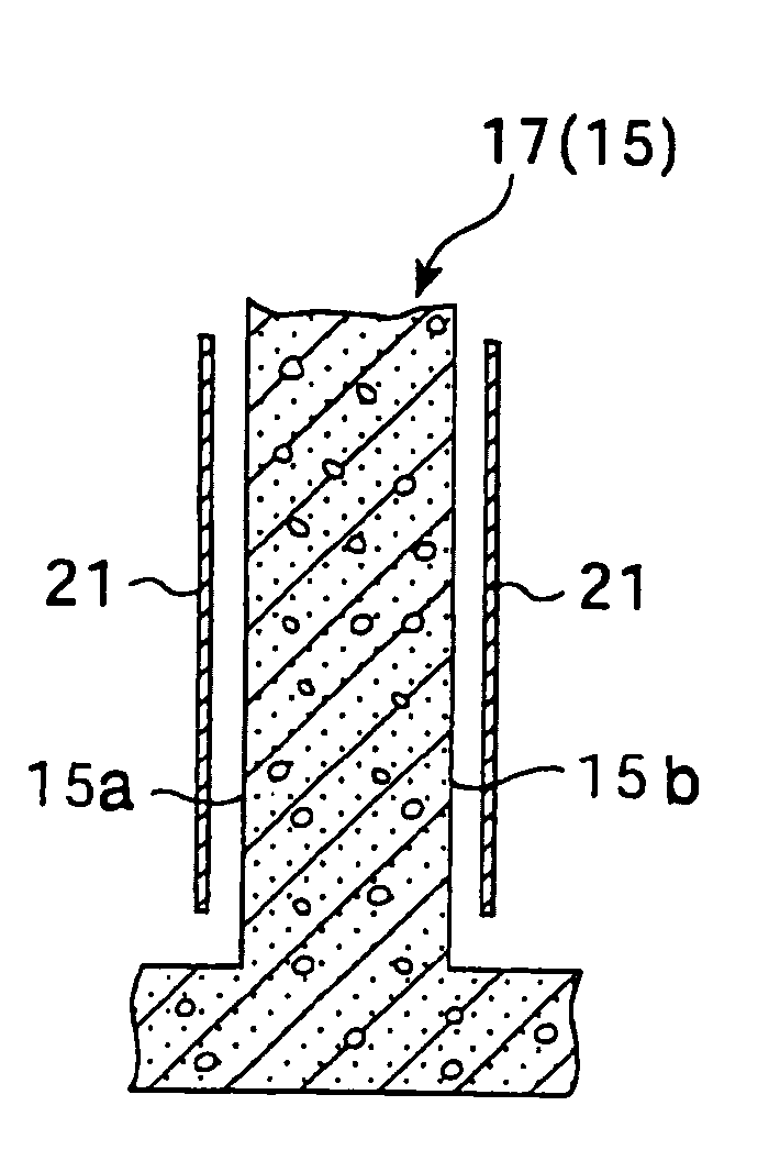
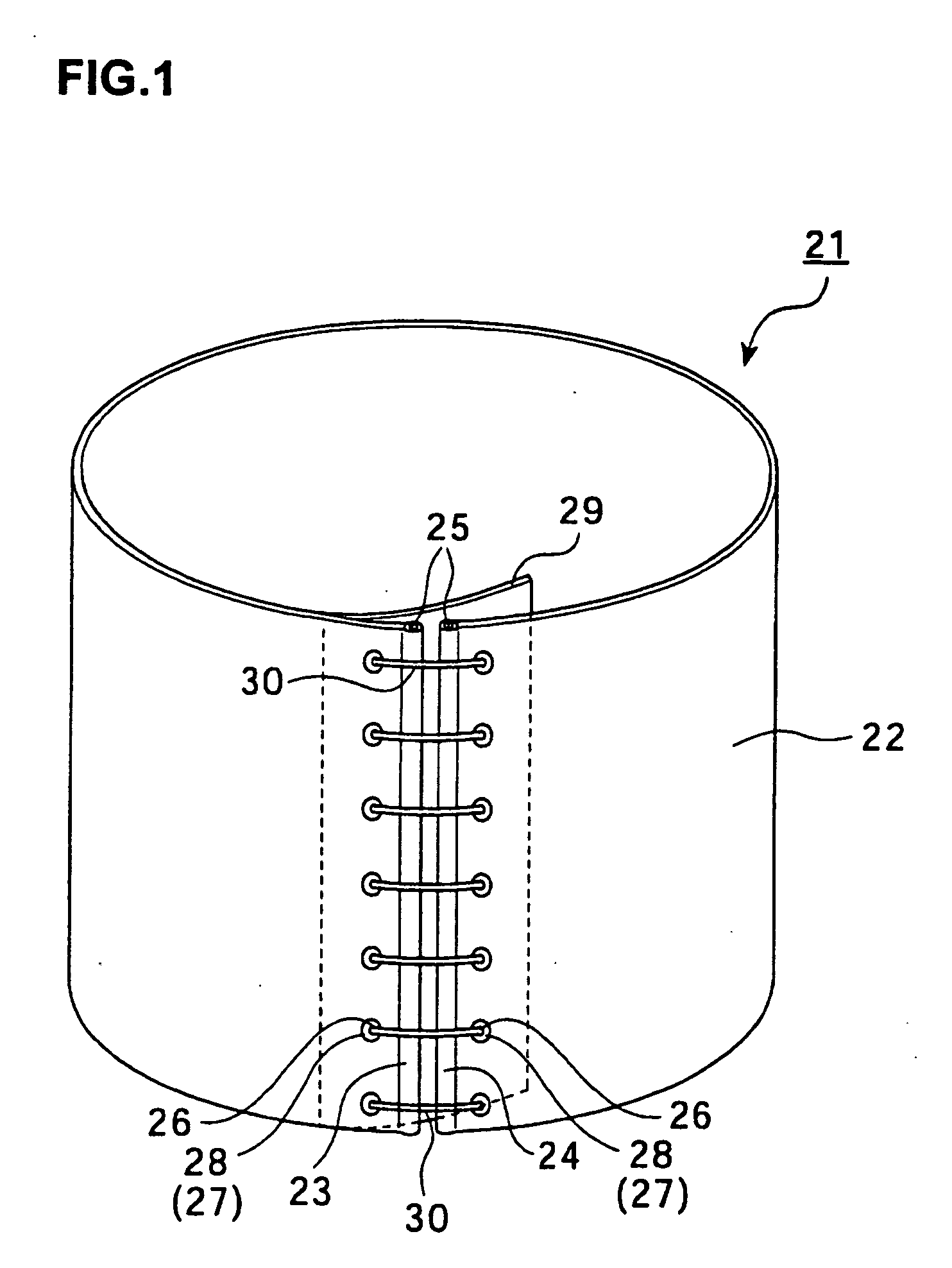
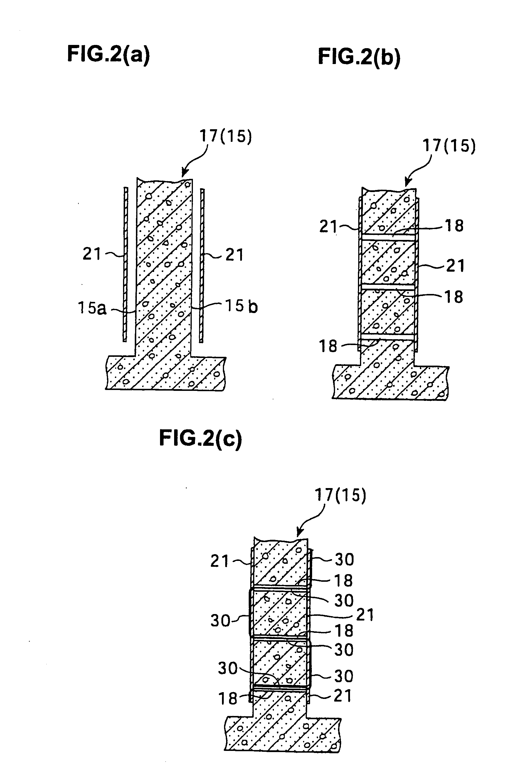
[0049]FIG. 1 is a general perspective view showing a structural example of a high-ductility material to be used in the present invention with various members, such as structural members, of a structure in order to control rupture of a member through confining volume expansion of the member accompanying rupture of the member.

[0050] As shown in FIG. 1, a high-ductility material 21 includes a sheet portion 22 having an appropriate longitudinal length and an appropriate width and serving as a main boy, one end portion 23, and the other end portion 24, the end portions 23 and 24 butting each other in the circumferential direction.

[0051] Core cords 25 are disposed respectively at one end portion 23 and the other end portion 24 of the sheet portion 22 in such a manner as to thread through the end portions 23 and 24 along the longitudinal-length direction. The core cord 25 reinforce one end portion 23 and the other end portion 24 to thereby enhance durability in the tensile direction.

[00...


PUM

PropertyMeasurementUnit
thicknessaaaaaaaaaa
lengthaaaaaaaaaa
areaaaaaaaaaaa

Abstract

A high-ductility material or a high-ductility covering material is disposed on the outer circumferential surface of a member, such as a column, of a structure so as to confine expansion of apparent volume accompanying rupture of the member, to thereby control rupture of the member. The high-ductility material is a fibrous or rubber sheet material. The high-ductility material is disposed in such a manner as to surround the member. Alternatively, the high-ductility material is spirally wound or rolled on the member.

Description

CROSS-REFERENCE TO RELATED APPLICATION [0001] This application is a continuation application of U.S. patent application Ser. No. 10 / 089,108 filed Mar. 26, 2002.TECHNICAL FIELD [0002] The present invention relates to a method, configuration, and material for reinforcing a structure for preventing serious damage to people and property in and around the structure, which would otherwise result from collapse of the structure, even after members (structural components, such as beams, girders, slabs, walls, and columns) of buildings and infrastructures (hereinafter generically called a “structure”) are visibly deformed due to rupture thereof caused by an abruptly imposed external force, such as a seismic force or wind force or an excessive load accompanying demolition, or caused by deficiency in yield strength stemming from deterioration. BACKGROUND ART [0003] An external force imposed abruptly by earthquake or the like, or deficiency in yield strength stemming from deterioration has repea...

Claims


Application Information

Patent Timeline
Patent Type & Authority Applications(United States)
IPC IPC(8): E04G23/02
CPCE04G23/0218E04G2023/0251E04G23/0225E04G2023/0262Y10T428/249953Y10T428/249921Y10T428/249924
Inventor IGARASHI, SHUNICHI
Owner IGARASHI SHUNICHI
Why Eureka
Try Eureka