Ignition device for internal combustion engine

Inactive Publication Date: 2005-12-29
DENSO CORP
View PDF10 Cites 19 Cited by
  • Summary
  • Abstract
  • Description
  • Claims
  • Application Information

AI Technical Summary

Problems solved by technology

The ignition device disclosed in U.S. Pat. No. 6,694,958-B, however, has an issue that a stress generated by mechanical vibrations of the internal combustion engine may snap the housing 1 a boundary between a fastened portion screw-fastened to t

Method used


Image

  • Ignition device for internal combustion engine
  • Ignition device for internal combustion engine
  • Ignition device for internal combustion engine

Examples


first embodiment

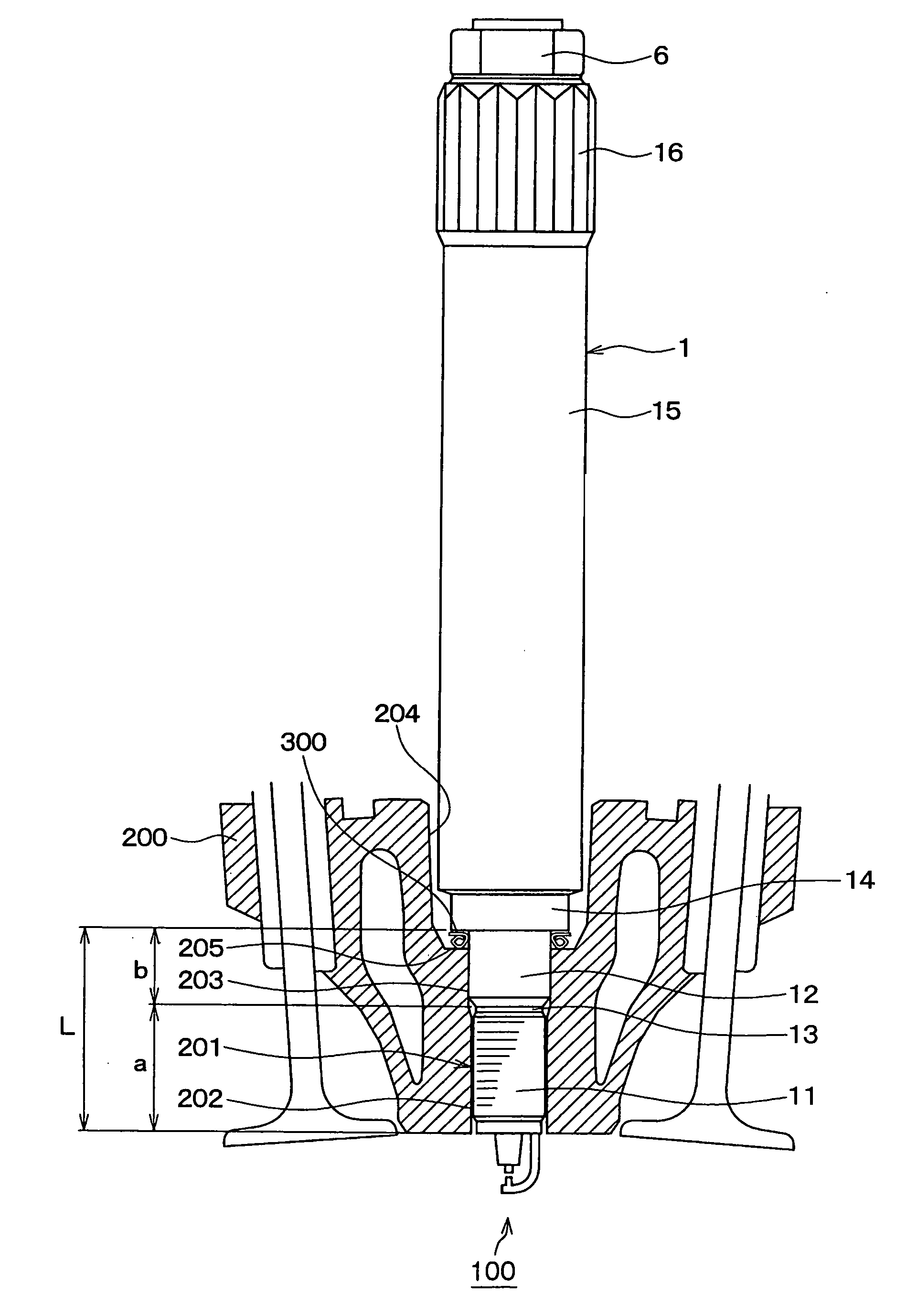
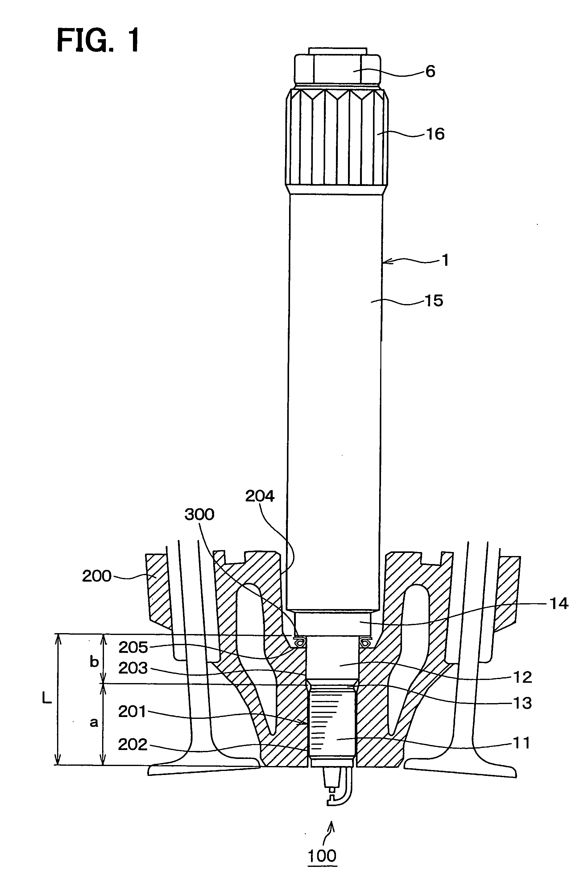
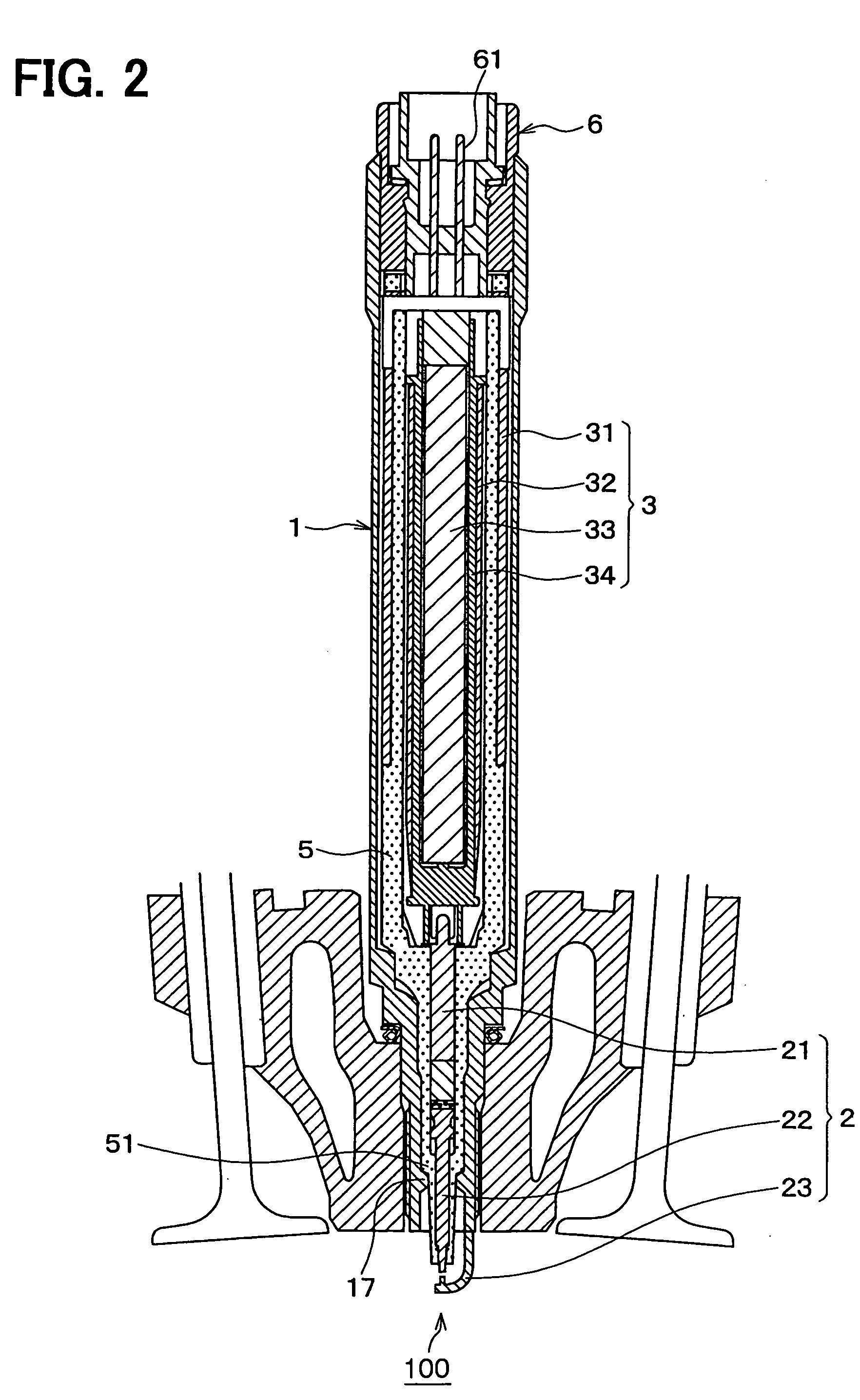
[0016] FIGS. 1 to 3 depict an ignition device according to a first embodiment of the present invention. The ignition device has a cylinder-shaped housing 1, a spark plug 2 and an ignition coil 3. The housing 1 encloses the spark plug 2 and the ignition coil 3 therein. The ignition device is mounted on a mounting hole 201 of a cylinder head 200 of an internal combustion engine to expose both terminals of the spark plug 2 in a combustion chamber of the internal combustion engine. The cylinder head 200 is made of aluminum.

[0017] The mounting hole 201 of the cylinder head 200 has a step as shown in FIGS. 1 and 2. The mounting hole 201 includes a female screw portion 202 formed at its end portion at a side of a combustion chamber 100 and a non-screw portion 203 formed between the step and the female screw portion 202. The non-screw portion 203 has a cylindrical shape and a bore diameter larger than a core diameter of the female screw portion 202. The cylinder head 200 further has a inst...

second embodiment

[0030]FIG. 5 depicts a principal portion of an ignition device according to a second embodiment of the present invention. In the ignition device according to the second embodiment, the outer circumferential face of the non-screw portion 12 and the end face 14a of the middle diameter portion are connected by a curved side circumferential face to decrease a stress concentration at a boundary between the non-screw portion 12 and the middle diameter portion 14. Thus, the strength at the boundary between the non-screw portion 12 and the middle diameter portion 14 can be still further large to prevent the housing 1 from snapping more securely.

[0031] A radius of curvature R of the curved side circumferential face is set between 0 mm and 1 mm to prevent an interference between the curved side circumferential face and the gasket ring 300 and to increase the strength at the boundary.

Other Embodiments

[0032] Although in the above-described embodiments the non-screw portions 12, 203 of the ho...


PUM


Abstract

An ignition device for an internal combustion engine has a spark plug, an ignition coil, a housing and a mounting portion. The spark plug is for discharging a current to ignite an air-fuel mixture in a combustion chamber of the internal combustion engine. The ignition coil is for supplying the current to the spark plug. The housing encloses the spark plug and the ignition coil therein. The housing has a mounting portion to be disposed in a mounting hole provided in a cylinder head of the internal combustion engine. The mounting portion includes a screw portion a non-screw portion. The screw portion is to be screw-fastened to the mounting hole. The non-screw portion is not to be screw-fastened to the mounting hole.

Description

CROSS REFERENCE TO RELATED APPLICATION [0001] This application is based on Japanese Patent Applications No. 2004-152171 filed on May 21, 2004 and No. 2005-042260 filed on Feb. 18, 2005, the contents of which is incorporated herein by reference. FIELD OF THE INVENTION [0002] The present invention relates to an ignition device for an internal combustion engine merging a spark plug for sparking in a spark gap and an ignition coil for supplying a large voltage current to the spark plug. BACKGROUND OF THE INVENTION [0003] Conventionally, an ignition device is known which merges a spark plug and an ignition coil in one housing as disclosed in U.S. Pat. No. 6,694,958-B and its counterpart JP-2003-297654-A for example. As shown in FIGS. 6 and 7, the ignition device has a male screw portion 22 formed on a housing 1 thereof to mount itself on an internal combustion engine. The male screw portion 22 is screw-fastened to a female screw portion 202 formed on a mounting hole 201 of a cylinder hea...

Claims


Application Information

Patent Timeline
IPC IPC(8): F02P1/00F02P3/02H01F27/06H01F38/12H01T13/08H01T13/44
CPCF02P3/02H01F27/06H01T13/44H01F2038/122H01T13/08H01F38/12
Inventor IWAMI, ATSUSHIMIWA, TETSUYAHIRAMATSU, HIROMIMORITA, YOSHIKI
Owner DENSO CORP
Why Eureka
Try Eureka