
Operating room control system

a control system and operating room technology, applied in the direction of electric controllers, instruments, applications, etc., can solve the problems of not linking with nonmedical devices or audio-visual equipment, adding to the complexity of the surgeon's work, and surgeons not being able to control an audio-visual device by themselves when he desires

Inactive Publication Date: 2005-12-29
OLYMPUS CORP
View PDF9 Cites 73 Cited by
  • Summary
  • Abstract
  • Description
  • Claims
  • Application Information

AI Technical Summary

Benefits of technology

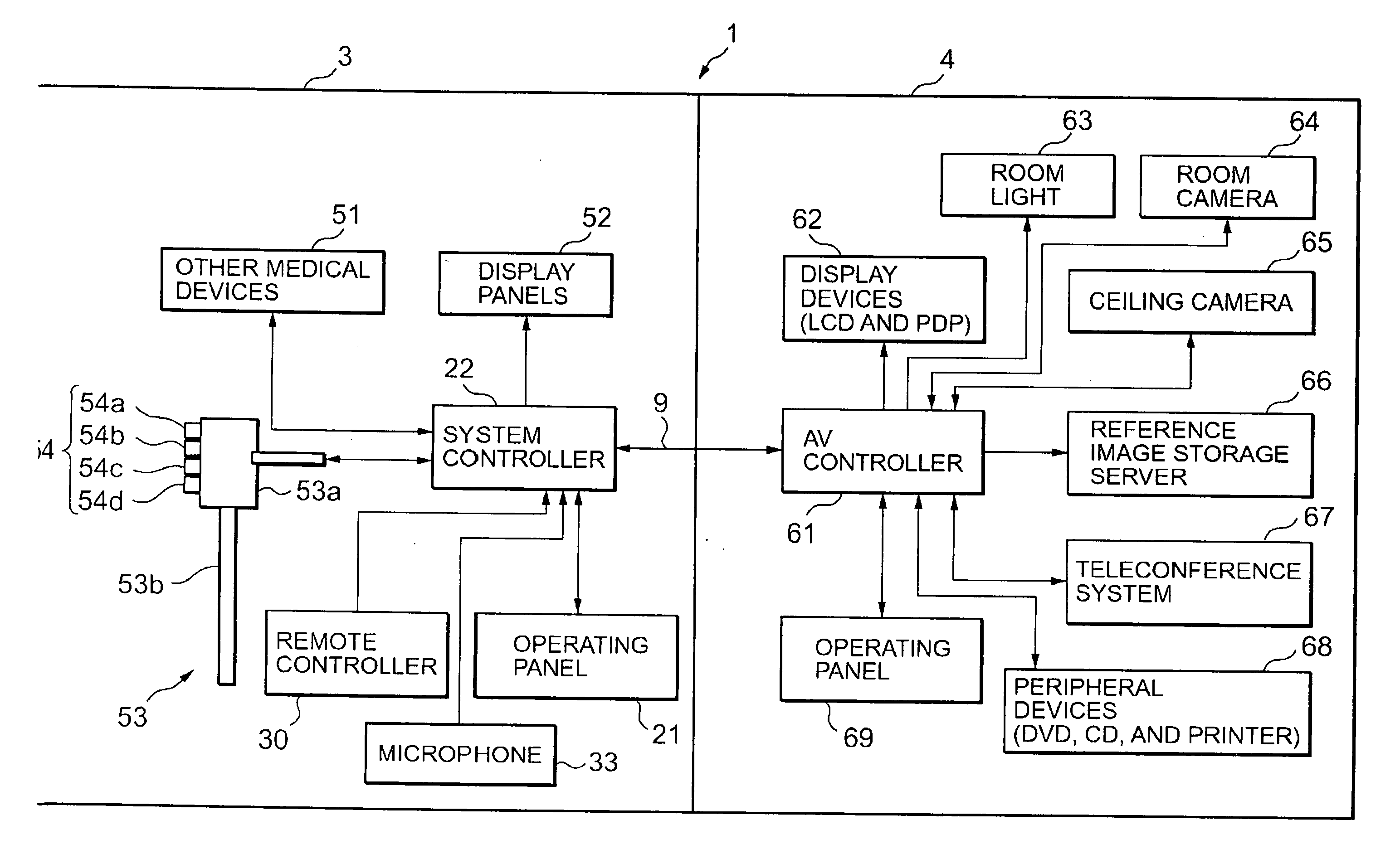
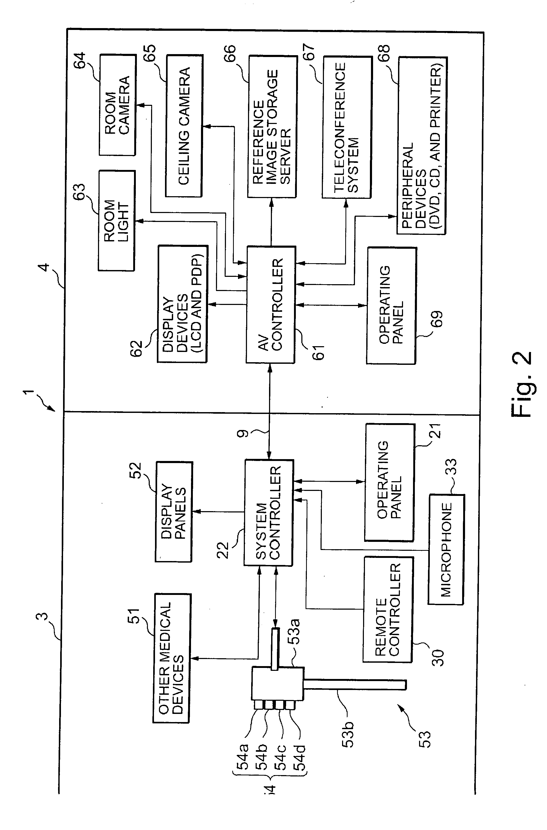
The present invention provides an operating room control system that allows a surgeon to operate nonmedical devices, such as room light, camera, and image recording device, by themselves. The system includes a first controller connected to the medical devices and a second controller connected to the nonmedical devices. The operating instruction input device receives the operating instruction for both the medical and nonmedical devices, and the first controller transmits the operating instruction to the second controller. The second controller converts the first control signal to a second control signal for controlling the nonmedical devices and transmits it to the nonmedical device. This allows the surgeon to operate the nonmedical devices easily and reduces operating errors. The system also includes a display member for displaying the content of the operating instruction, making it easy for the surgeon to check the instruction.

Problems solved by technology

The aforementioned surgery system, however, does not link with the nonmedical devices or audio-visual equipment.
Such oral instructions to a nurse or other person in the operating room adds to the complexity of the surgeon's work and the surgeon cannot control an audio-visual device by himself when he desires.

Method used


Image

  • Operating room control system
  • Operating room control system
  • Operating room control system

Examples


Embodiment Construction

[0021] Preferred embodiments of the invention are described below with reference to the accompanying drawings.

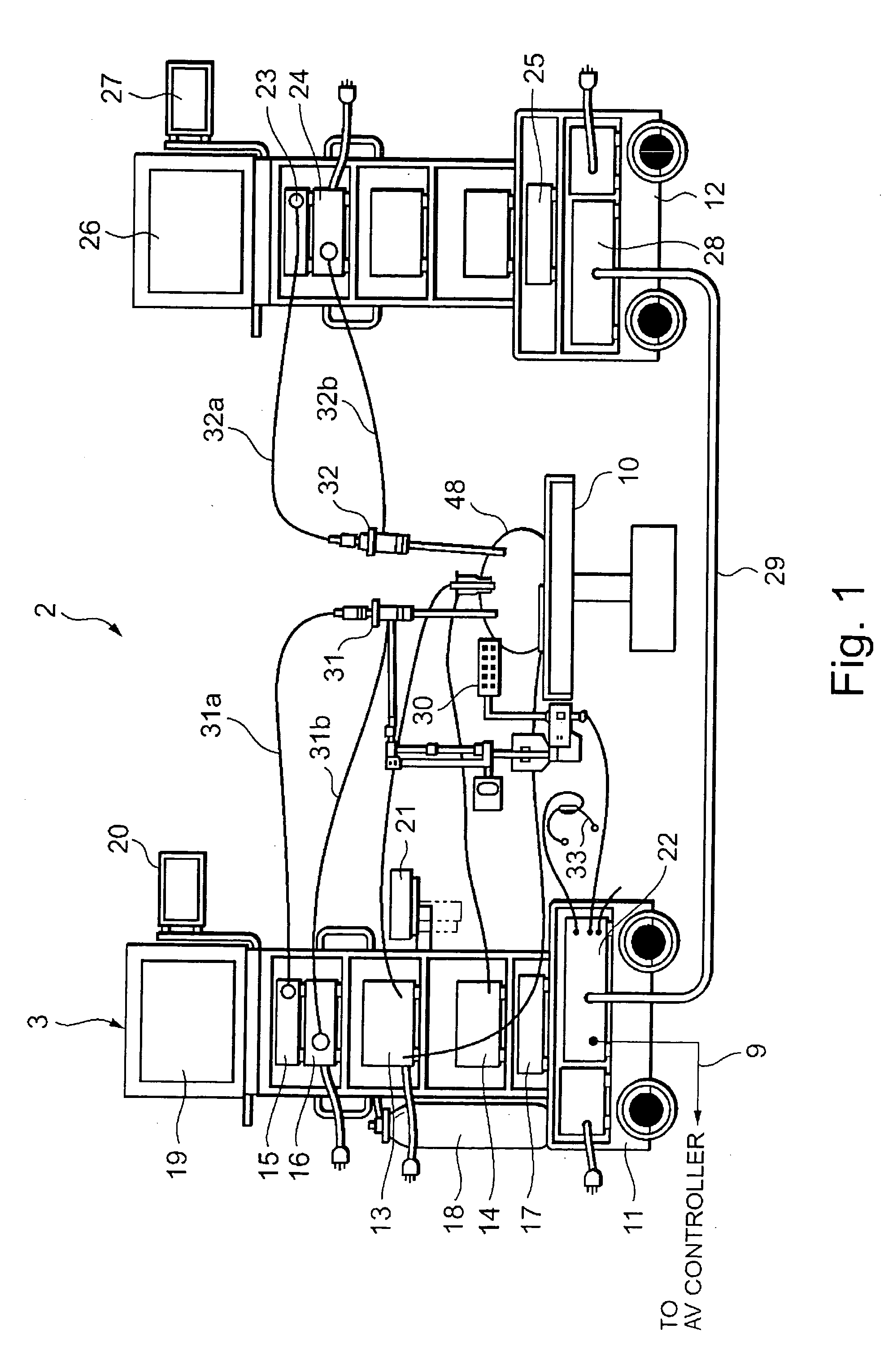
[0022] An operating room control system according to an embodiment comprises a plurality of medical devices and a system controller as a medical device controller. The description begins with an explanation of an endoscopic surgery system, which is one of the examples of a surgery system including a plurality of medical devices and a system controller for controlling these medical devices. Referring to FIG. 1, there is shown a schematic diagram illustrating a configuration of an endoscopic surgery system 3 placed in an operating room 2.

[0023] As shown in FIG. 1, a patient's bed 10 on which a patient 48 is laying and the endoscopic surgery system 3 are placed in the operating room 2. The endoscopic surgery system 3 has a first cart 11 and a second cart 12.

[0024] The first cart 11 is loaded with medical devices as controlled devices such as, for example, an electric cautery...


PUM


Abstract

An operating room control system including: a first controller connected to a medical device placed in an operating room; a second controller connected to a nonmedical device placed in the operating room; and an operating instruction input device for accepting input of an operating instruction for the medical device and for transmitting the content of the entered operating instruction to the first controller. In this operating room control system, an operating instruction for the nonmedical device is also entered into the operating instruction input device. The first controller transmits a first control signal according to the operating instruction for the nonmedical device entered into the operating instruction input device to the second controller. The second controller converts the first control signal to a second control signal for controlling the nonmedical device and transmits it to the nonmedical device. Thereby, a surgeon can operate the nonmedical device by himself.

Description

CROSS-REFERENCE TO RELATED APPLICATION [0001] This application is based upon and claims the benefit of priority from prior Japanese Patent Application No. 2004-182132, filed Jun. 21, 2004, the entire contents of which is incorporated herein by reference. BACKGROUND OF THE INVENTION [0002] 1. Field of the Invention [0003] The present invention relates to an operating room control system, and more particularly to an operating room control system in which a surgeon or the like can operate nonmedical devices. [0004] 2. Description of the Related Art [0005] Conventionally, there has been suggested a surgery system in which a system controller controls medical devices including an endoscope used in a surgery (Refer to FIG. 1 in Laid-Open Japanese Patent Publication No. 2004-157177, for example). The system controller is connected to, for example, an electric cautery, an insufflator, an endoscopic camera, and a light source as medical devices, which are controlled devices. The system contr...

Claims


Application Information

Patent Timeline
Patent Type & Authority Applications(United States)
IPC IPC(8): A61B17/00A61B90/00A61B90/30G05B11/01G05B15/02G06F13/28G06F17/00
CPCA61B17/00234A61B19/52G05B15/02A61B2017/00017A61B19/5225A61B90/36A61B90/37
Inventor TASHIRO, KOICHINAKAMURA, TAKEAKIUCHIKUBO, AKINOBU
Owner OLYMPUS CORP
Learn More