Vibration reduction apparatus for power tool and power tool incorporating such apparatus

a technology of vibration reduction and power tools, which is applied in the direction of portable percussive tools, portable power-driven tools, multi-purpose tools, etc., can solve the problems of dampening vibrations caused, damage to the apparatus itself, harming the users of the apparatus, etc., and achieves the effect of reducing the likelihood of non-linear vibrations

Inactive Publication Date: 2005-12-29
BLACK & DECKER INC
View PDF47 Cites 32 Cited by
  • Summary
  • Abstract
  • Description
  • Claims
  • Application Information

AI Technical Summary

Benefits of technology

[0032] By situating the springs and body portions within a tubular body portion the advantage is provided that the handle is constrained to move linearly relative to the housing thereby reducing the likelihood of non-linear vibrations such as rocking of the handle relative to the housing.

Problems solved by technology

Known hammer drills of this type suffer from the drawback that the hammer action generates significant vibrations, which can be harmful to users of the apparatus, and can cause damage to the apparatus itself.
This in turn causes the compression of first spring 110 and dampens vibrations which are caused by the hammer action of the power tool.
Dampening devices of this type suffer from the disadvantage that the transition from the dampening of a single spring to both springs is abrupt, causing additional vibration in the handle which must be absorbed by the user.

Method used


Image

  • Vibration reduction apparatus for power tool and power tool incorporating such apparatus
  • Vibration reduction apparatus for power tool and power tool incorporating such apparatus
  • Vibration reduction apparatus for power tool and power tool incorporating such apparatus

Examples


Embodiment Construction

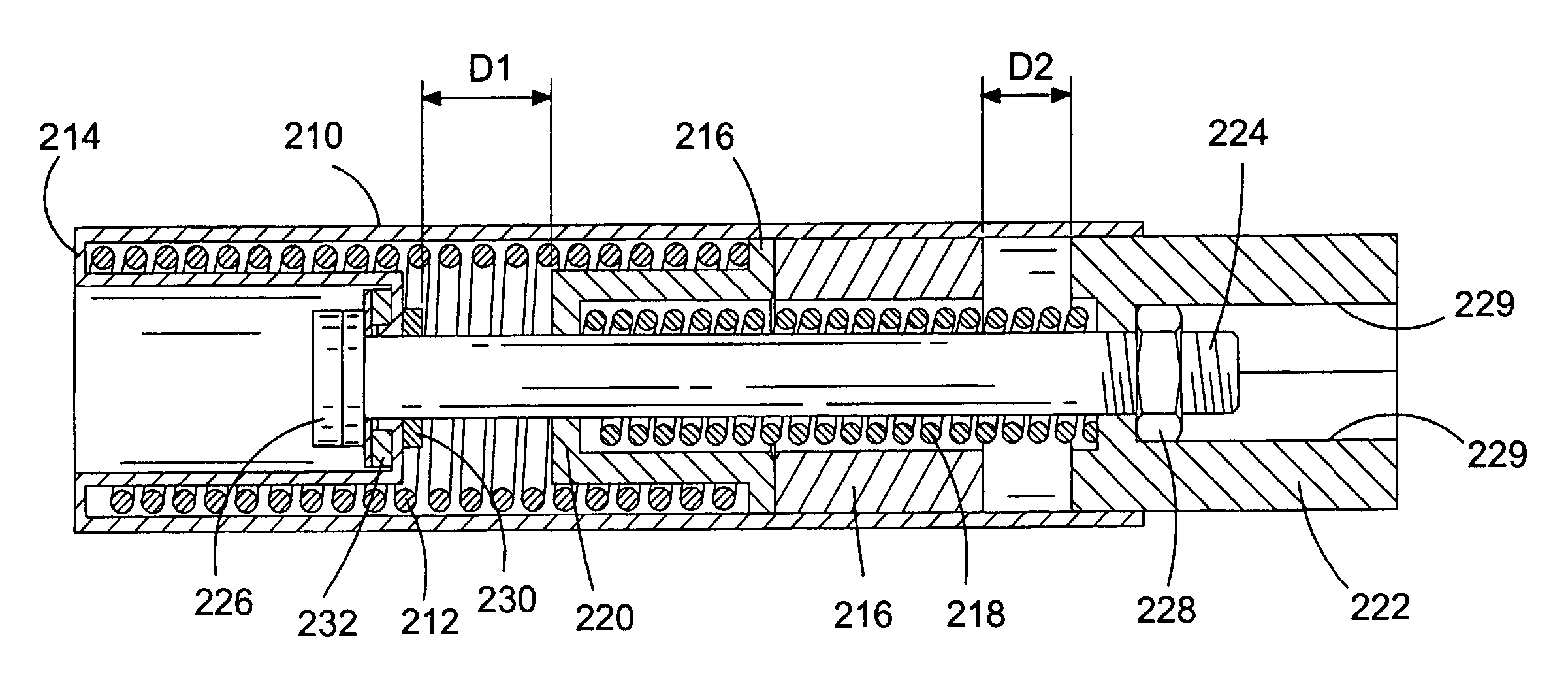
[0042] Referring to FIG. 3, a handle assembly for a power tool, for example a hammer or drill including a hammer action, includes a first substantially tubular body portion 210 which contains a first biasing element, first spring 212. First spring 212 is retained at one end by an end portion 214 of first body 210 and at the other end by second body portion 216 which is slidably mounted within first body portion 210. Second body portion 216 contains a second biasing element, second spring 218, which is retained at one end by end portion 220 of second body portion 216. The other end of second spring 218 is retained by third body portion 222. The biasing coefficient, or spring constant, of the first spring 212 is less than that of the second spring 218. This means that the first spring 212 is softer, and therefore more easily compressed, than the second spring 218.

[0043] The first, second and third body portions 210, 216 and 222, and first and second springs, 212 and 218, are all moun...


PUM


Abstract

A handle assembly for a power tool is described and includes a first substantially tubular body portion 210 which contains a first spring 212. A second body portion 216 is slidably mounted within first body portion 210 and contains a second spring 218. A third body portion 222 is also slidably mounted within first body portion 210. The biasing coefficient, or spring constant, of the first spring 212 is less than that of the second spring 218. The first, second and third body portions 210, 216 and 222, and first and second springs, 212 and 218, are all mounted coaxially on threaded bolt 224. In use the third body portion 222 moves within first body portion 210 in a direction towards end portion 214 and the first and softer spring 212 becomes compressed more rapidly than the second and harder spring 218. When the distance D1 has reduced to zero, by compression of first spring 212, the rubber washer 230 engages end portion 220 of second body portion 216 and the biasing effect of first spring 212 is eliminated The biasing force of the harder second spring 218 acts alone up to a distance D2.

Description

FIELD OF THE INVENTION [0001] The present invention relates to vibration reduction apparatus for power tools and to power tools incorporating such apparatus. The invention relates particularly, but not exclusively, to vibration reduction apparatus for power hammers, and to hammers incorporating such apparatus. BACKGROUND OF THE INVENTION [0002] Electrically driven hammers are known in which a driving member in the form of a flying mass is reciprocally driven by means of a piston, and impact of the flying mass against the end of the piston cylinder imparts a hammer action to a bit of the hammer. Such an arrangement is disclosed in European patent application EP1252976 and is shown in FIG. 1. [0003] Referring in detail to FIG. 1, the prior art demolition hammer comprises an electric motor 2, a gear arrangement and a piston drive arrangement which are housed within a metal gear housing 5 surrounded by a plastic housing 4. A rear handle housing incorporating a rear handle 6 and a trigge...

Claims


Application Information

Patent Timeline
Patent Type & Authority Applications(United States)
IPC IPC(8): B25D17/04B25D17/24B25F5/00
CPCB25D17/043Y10T16/48B25D2250/371B25D2250/005
Inventor BACILA, DORIN
Owner BLACK & DECKER INC
Why Eureka
Try Eureka