Assessing down-hole drilling conditions

Active Publication Date: 2005-12-29
INTELLISERV
View PDF64 Cites 81 Cited by
  • Summary
  • Abstract
  • Description
  • Claims
  • Application Information

AI Technical Summary

Problems solved by technology

The reasons are many, but the interest primarily arises from the fact that even minor interruptions in drilling operations can be quite expensive.
Many types of interruptions can be very expensive.
Gathering information about down-hole drilling conditions, however, can be a daunting challenge.
The down-hole environment is very harsh, especially in terms of temperature, shock, and vibration.
Furthermore, many drilling operations are conducted very deep within the earth, e.g., 20,000′-30,000′, and the length of the drill string causes significant attenuation in the signal carrying the data to the surface.
The difficulties of the down-hole environment also greatly hamper making and maintaining electrical connections down-hole, which impairs the ability to obtain large amounts of data down-hole and transmit it to the surface during drilling operations.
In general, data taken from the surface and only limited data taken from the surface and / or the bottom of the borehole is available.
Because the borehole might be as deep as 20,000′-30,000′, surface data frequently is not particularly helpful in these types of extrapolations.
The down-hole data can be more useful than surface data, but its utility is limited by its relatively small amount and the fact that it represents conditions localized at the bottom of the bore.
Thus, the down-hole data may be useful in detecting some conditions at the bottom of the borehole but of little use for other conditions at the bottom or along the length of the drill string.
Although conventional overbalanced drilling has been recognized as the safest method of drilling, it has several drawbacks.
Since the drilling fluid pressure is maintained higher than the formation's pore pressure, the formation is easily damaged by the intrusion of drilling fluids into the formation.
For example, overbalanced drilling may cause the blockage or washout of the formation structure.
In addition, because the drilling fluid pressure exceeds the formation's pore pressure, the penetration speed of the drill bit may actually decrease.
This occurs because cuttings produced by the drill bit are often inadequately removed in overbalanced systems, thereby causing the drill bit to rotate against the buildup of cuttings rather than penetrating through virgin rock.
This also decreases the life of the drill bit, thereby requiring more frequent drill bit replacement and loss of drilling time.
In underbalanced drilling applications, the drilling fluid pressure is maintained below the formation pore pressure.
Nevertheless, underbalanced drilling also presents certain challenges.
First, underbalanced drilling is more subject to blowouts, fires, and explosions caused by the formation pore pressure overwhelming the lower pressure of the drilling fluid.
Second, due to the precise control and monitoring needed, underbalanced drilling can be more expensive than conventional drilling.
Also, because of the decreased pressure, the removal of cuttings can be problematic, especially in directional drilling applications where the well deviates from vertical or is substantially horizontal.
For instance, one adverse drilling condition of interest is “stuck pipe.” As the drill sting bores through the earth, the borehole seldom descends straight into the earth.
There typically are many deviations from the vertical, and some may be very severe in some drilling applications.
In these situations, the sides of the borehole may bind the drill string causing it to become stuck within the borehole.
Once the drill string becomes stuck, it is quite costly to halt drilling operations and free the drill string.
Current techniques cannot provide this kind of information because the data they work from has insufficient granularity.

Method used


Image

  • Assessing down-hole drilling conditions
  • Assessing down-hole drilling conditions
  • Assessing down-hole drilling conditions

Examples


Embodiment Construction

[0039] Illustrative embodiments of the invention are described below. In the interest of clarity, not all features of an actual implementation are described in this specification. It will of course be appreciated that in the development of any such actual embodiment, numerous implementation-specific decisions must be made to achieve the developers' specific goals, such as compliance with system-related and business-related constraints, which will vary from one implementation to another. Moreover, it will be appreciated that such a development effort, even if complex and time-consuming, would be a routine undertaking for those of ordinary skill in the art having the benefit of this disclosure.

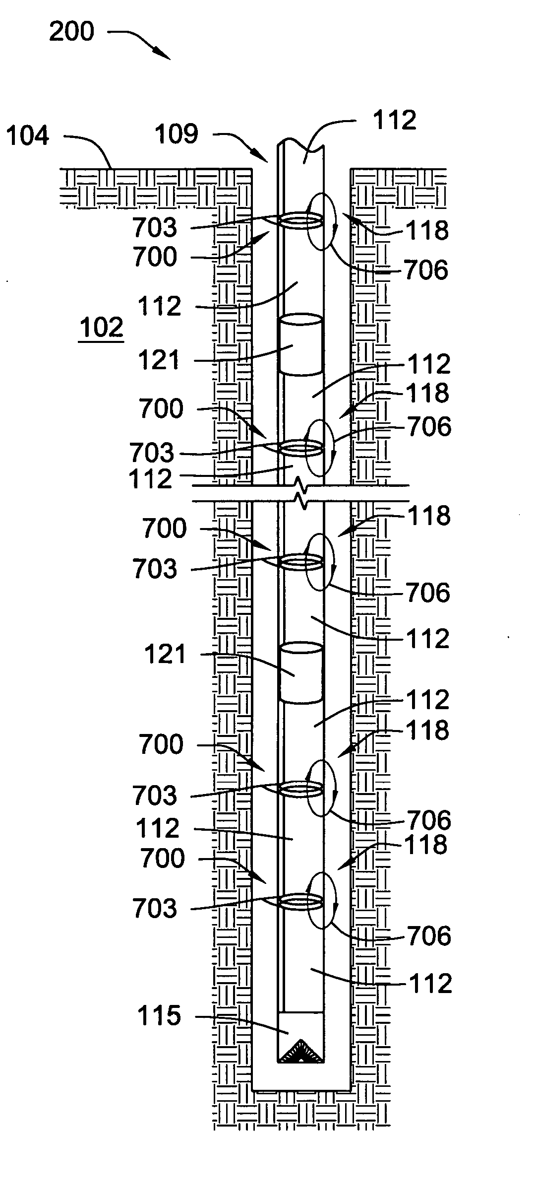
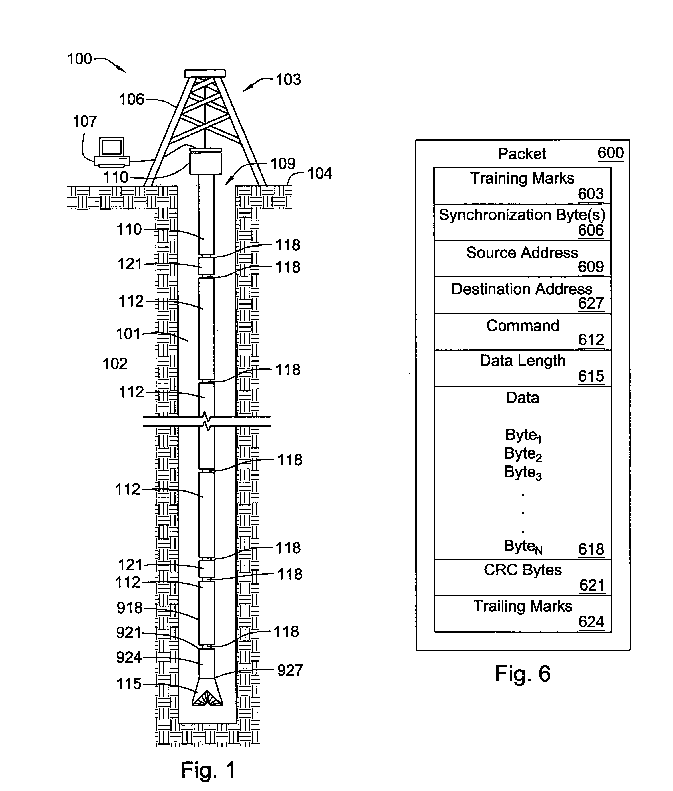
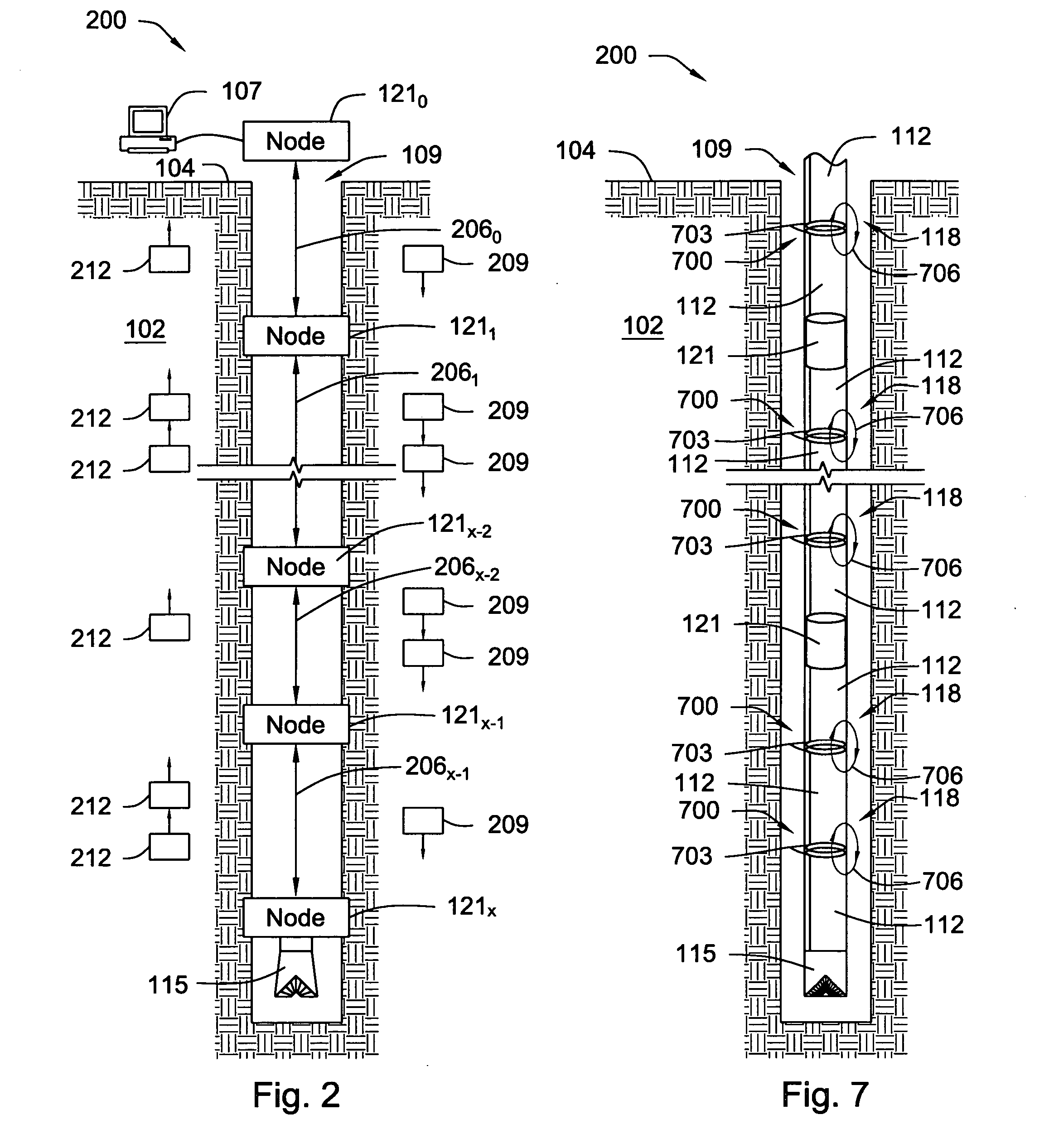
[0040] The invention comprises an apparatus and a method for use in assessing adverse, down-hole drilling conditions. In general, the apparatus comprises: [0041] a drill string (shown best in FIG. 1); [0042] a plurality of sensors (shown best in FIG. 5) distributed along the length of the drill...


PUM


Abstract

A method and apparatus for use in assessing down-hole drilling conditions are disclosed. The apparatus includes a drill string, a plurality of sensors, a computing device, and a down-hole network. The sensors are distributed along the length of the drill string and are capable of sensing localized down-hole conditions while drilling. The computing device is coupled to at least one sensor of the plurality of sensors. The data is transmitted from the sensors to the computing device over the down-hole network. The computing device analyzes data output by the sensors and representative of the sensed localized conditions to assess the down-hole drilling conditions. The method includes sensing localized drilling conditions at a plurality of points distributed along the length of a drill string during drilling operations; transmitting data representative of the sensed localized conditions to a predetermined location; and analyzing the transmitted data to assess the down-hole drilling conditions.

Description

[0001] This is a continuation-in-part of the following co-pending, commonly assigned applications: [0002] U.S. application Ser. No. 10 / 216,266, entitled “Load-Resistant Coaxial Transmission Line,” and filed Aug. 10, 2002, in the name of David R. Hall, et al.; [0003] U.S. application Ser. No. 10 / 315,263, entitled “Signal Connection for a Downhole Tool String (Swivel)”, and filed Dec. 10, 2002, in the name of the inventors David R. Hall, et al.; [0004] U.S. application Ser. No. 10 / 613,549, entitled “Link Module For a Downhole Drilling Network,” and filed Jul. 1, 2003, in the name of David R. Hall, et al.; and [0005] U.S. application Ser. No. 10 / 481,225, entitled “Downhole Network,” and filed Aug. 13, 2003, in the name of David R. Hall, et al. Each of these applications is hereby incorporated herein by reference for all purposes as if expressly set forth verbatim herein.U.S. GOVERNMENT INTEREST [0006] This invention was made with government support under Contract No. DE-FC26-01NT41229...

Claims


Application Information

Patent Timeline
IPC IPC(8): E21B47/026E21B47/12
CPCE21B47/122E21B47/13
Inventor HALL, DAVID R.PIXTON, DAVID S.JOHNSON, MONTE L.BARTHOLOMEW, DAVID B.FOX, JOE
Owner INTELLISERV
Why Eureka
Try Eureka