Resistance welding device

a welding device and resistance technology, applied in the direction of resistive welding apparatus, soldering auxiliary devices, welding electric supplies, etc., can solve the problem of high heat, and achieve the effect of limiting the maximum travel and preventing turning

Active Publication Date: 2005-12-29
TAMP ING EUROPA SUR
View PDF5 Cites 7 Cited by
  • Summary
  • Abstract
  • Description
  • Claims
  • Application Information

AI Technical Summary

Problems solved by technology

The considerable resistance that exists between the surfaces in contact with the two parts and the high current that passes produces a high degree of heat that melts the surrounding material, thus making the weld.
This is due to the fact that during the pressing cycle a pair of electrodes facing each other is not in a position to be able to carry out the resistance for the time necessary with the correct pressure.

Method used


Image

  • Resistance welding device
  • Resistance welding device
  • Resistance welding device

Examples


Embodiment Construction

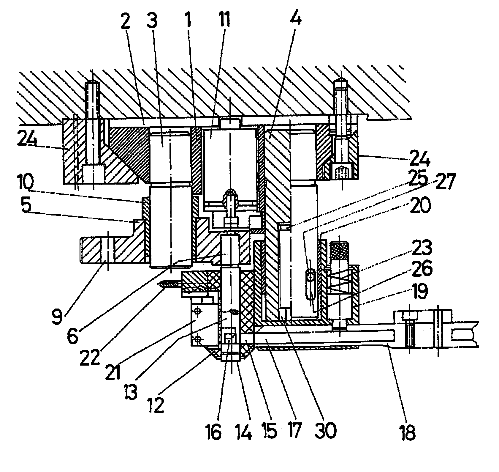
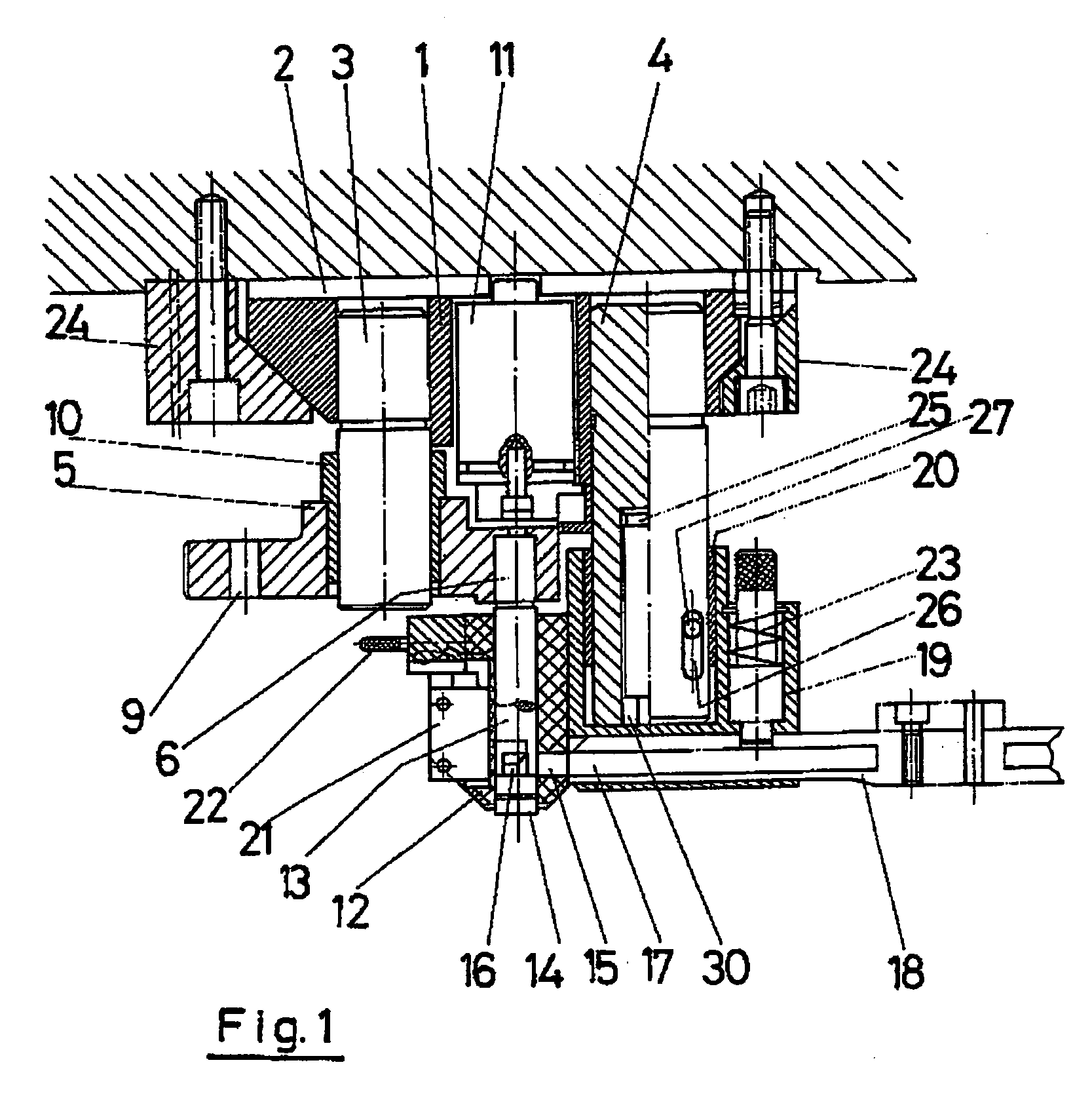
[0008] The improved device for welding by resistance that is the purpose of this invention is characterised in that it includes a two part electrode assembly that form a clamp and allow it to work as an intermediary welding step in a progressive press machine or transfer stamping machine or automated drawing. However, the use of said device in the clamps of robots and other mechanisms suitable for its use is not dismissed.

[0009] The device mainly seeks to obtain two advantages, consistent with the obtaining of sufficient welding pressure for an exact time without the pressing cycle being altered with stoppages in order to carry out said weld and the automatic placing of the parts to be welded onto the sheet or plate that is being pressed or deep drawn.

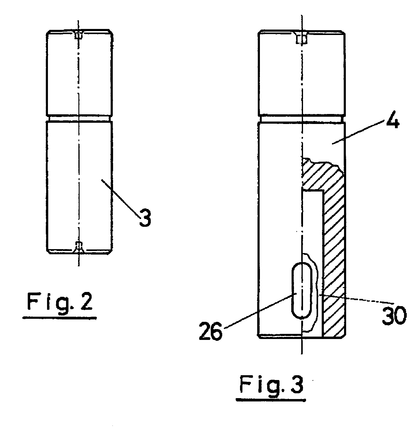
[0010] In effect the device forms a welding assembly together with another electrode holding the parts to be welded and that allows the circulation of the welding current through it. Each one of the electrodes is fixed in one of the ...


PUM

PropertyMeasurementUnit
resistanceaaaaaaaaaa
compression forceaaaaaaaaaa
movementaaaaaaaaaa

Abstract

IMPROVED RESISTANCE WELDING DEVICE that includes a mobile electrode in a support assisted by a spring, gas cylinder or expansion element, allowing its movement on being compressed so that the time lapse for the welding is sufficiently long to be effective, without altering the movement cycle of the press into which it is installed. The support has one or several columns, the electrode being supported sliding along one and with a rod housed on the inside of a positioning device, also axially movable, into which the small parts to be welded are received through a conduit. The positioning device, made from an insulated material, preferably ceramic, has some fixing clamps for said part until the welding is made pushed by the electrode rod through a lower window.

Description

OBJECT OF THE INVENTION [0001] The object of the present Invention is an improved device for welding by resistance that comprises significant innovations and advantages compared to the present fixtures and devices for resistance welding of small metallic parts and similar objects. [0002] More specifically the new invention refers to a fixture that has an electrode for the welding of small parts and similar objects in transfer machines or rotating presses amongst other applications. The device is made up of a movable electrode in a support assisted by a gas cylinder, spring or compression element, allowing the time lapse of the weld to be sufficiently longs so that it is effective, without altering the movement cycle of the press in which it is installed. This device is held in place by a fast acting clamp and works in coordination with a conventional electrode arranged in the lower die or matrix. The device can also be used in multi-use clamps of robots and other machines. BACKGROUN...

Claims


Application Information

Patent Timeline
Patent Type & Authority Applications(United States)
IPC IPC(8): B23K11/00B23K11/14B23K11/30B23K11/31
CPCB23K11/004B23K11/0053B23K11/318B23K11/3081B23K11/31B23K11/14B23K11/253B23K11/241B23K11/3018B23K37/003Y10S29/013
Inventor MARTIN GONZALEZ, IGNACIO
Owner TAMP ING EUROPA SUR
Why Eureka
Try Eureka