

Tub construction for dishwasher
a technology for dishwashers and tubs, applied in the field of dishwasher tub construction, can solve the problems of reducing productivity, difficult to change the dimensions of the tub, and the lengthening of the tub process, and achieve the effect of fast tim
- Summary
- Abstract
- Description
- Claims
- Application Information
AI Technical Summary
Benefits of technology
Problems solved by technology
Method used
Image

Examples
Embodiment Construction
[0030] Reference will now be made in detail to the preferred embodiments of the present invention, examples of which are illustrated in the accompanying drawings. Wherever possible, the same reference numbers will be used throughout the drawings to refer to the same or like parts.
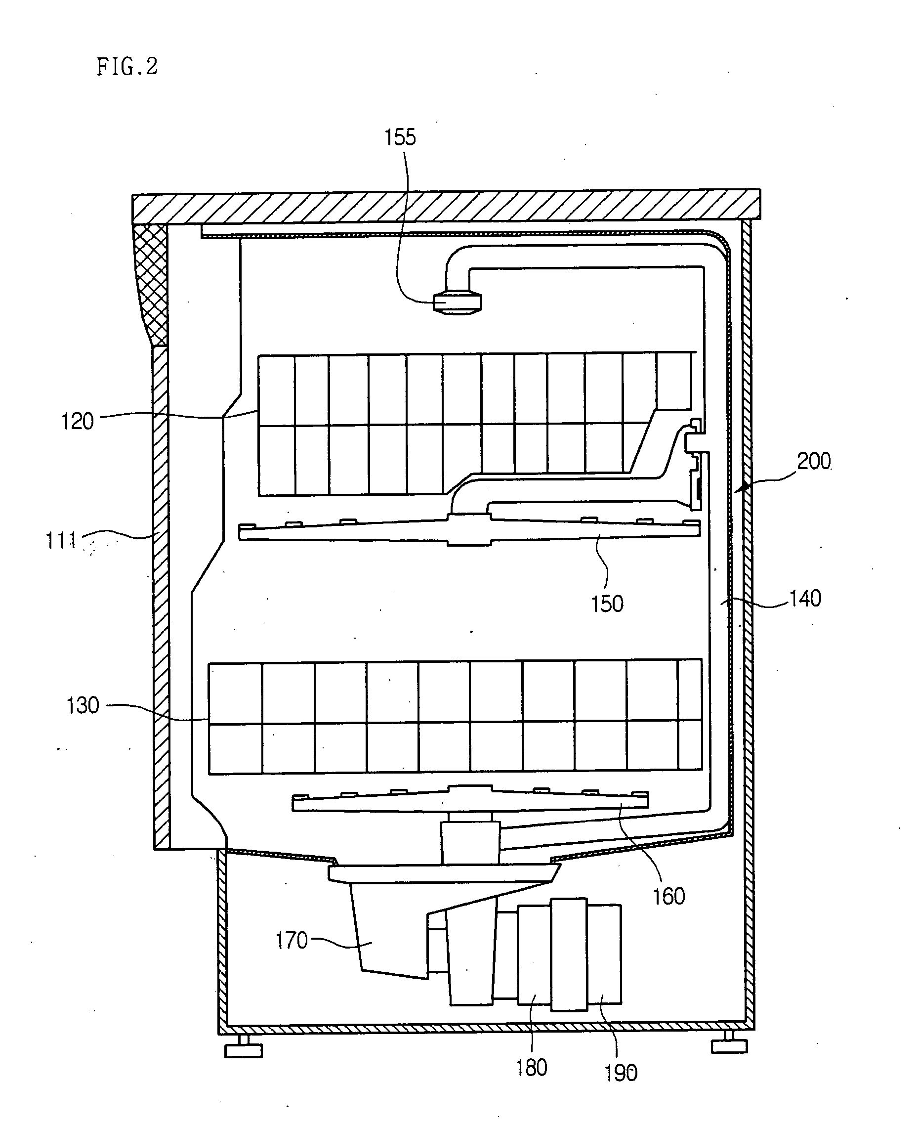
[0031]FIG. 2 is a sectional view of a dishwasher with a tub according to an embodiment of the present invention.
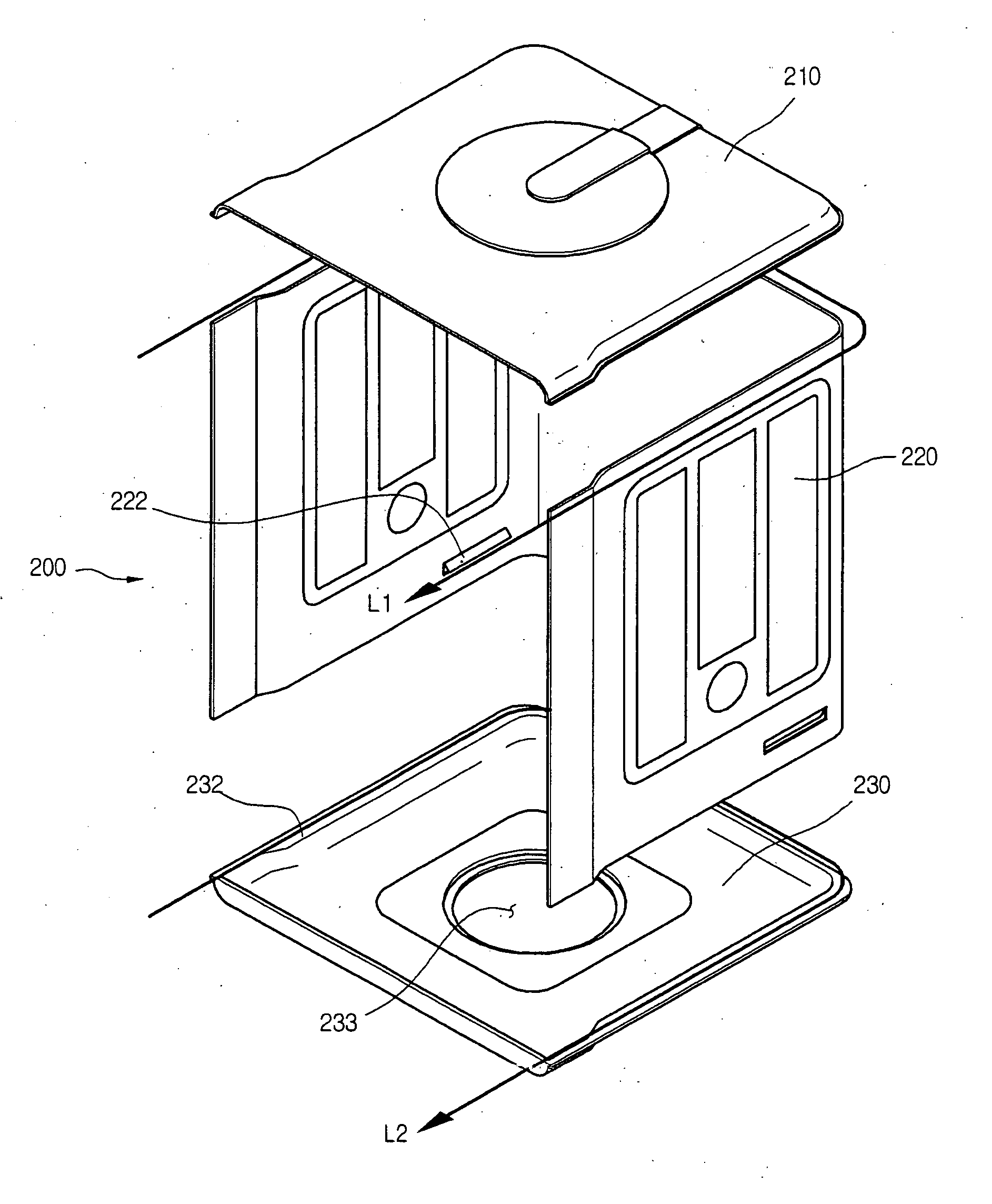
[0032] Referring to FIG. 2, a dishwasher having the tub construction of the present invention has a tub 200 forming an exterior and having dishwasher parts formed therein, a door 111 pivotably formed to open and close at the front of the tub 200, and a sump 170 formed at the central bottom portion of the tub 200 for holding washing water.
[0033] Also, a wash pump 180 is connected to the sump 170 for high-pressure pumping of the washing water stored in the sump 170, and a motor 190 attached to the rear of the wash pump 180 for driving the wash pump 180.
[0034] In addition, the dishwasher includes...
PUM
 Abstract
Description
Claims
Application Information