
Universal waveguide interface adaptor

a waveguide and interface technology, applied in waveguide devices, basic electric elements, electrical apparatuses, etc., can solve problems such as reflected power, high vswr, and problems such as problems such as problems such as affecting the performance of the waveguid

Inactive Publication Date: 2005-12-29
ANDREW CORP
View PDF19 Cites 24 Cited by
  • Summary
  • Abstract
  • Description
  • Claims
  • Application Information

AI Technical Summary

Benefits of technology

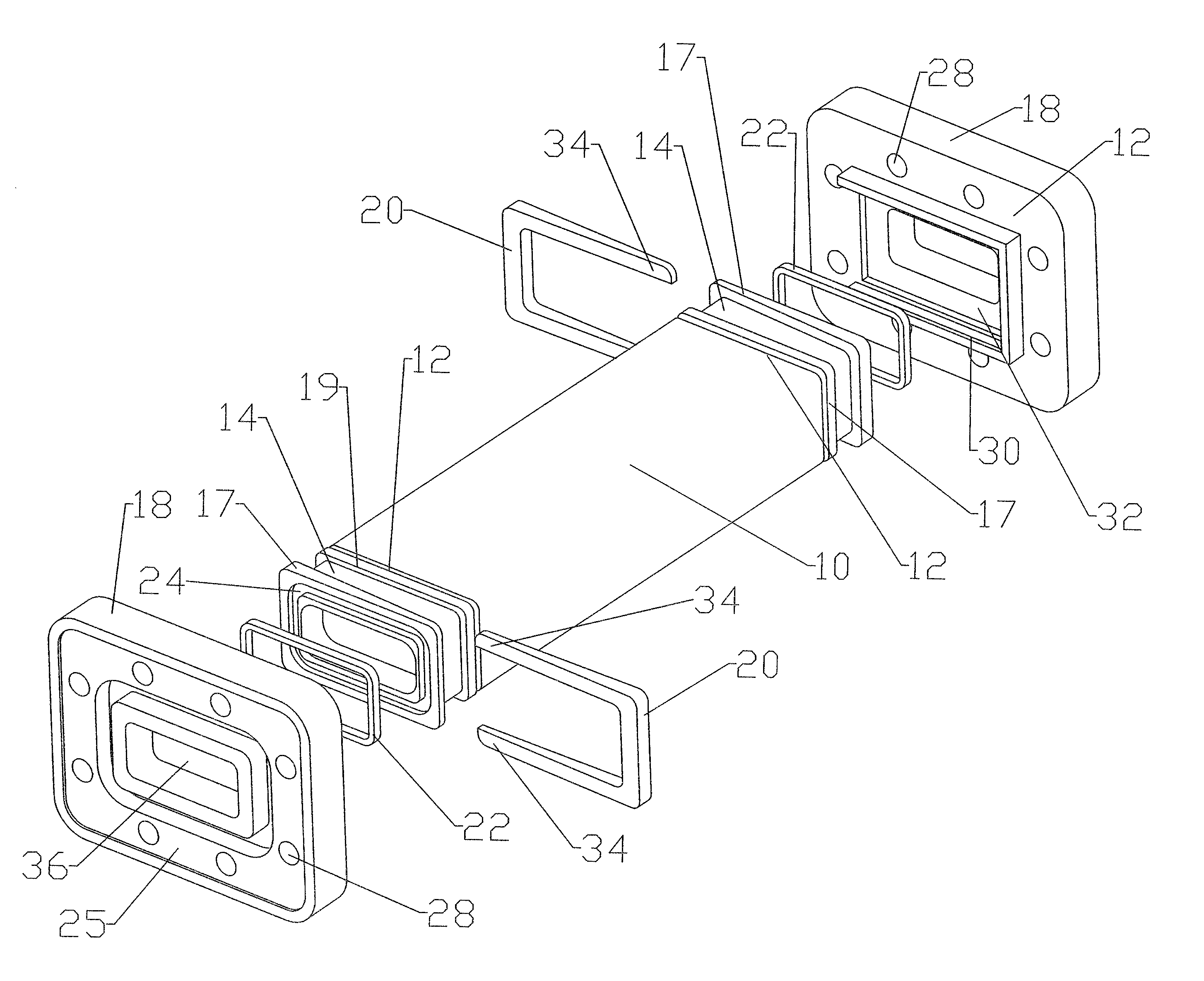
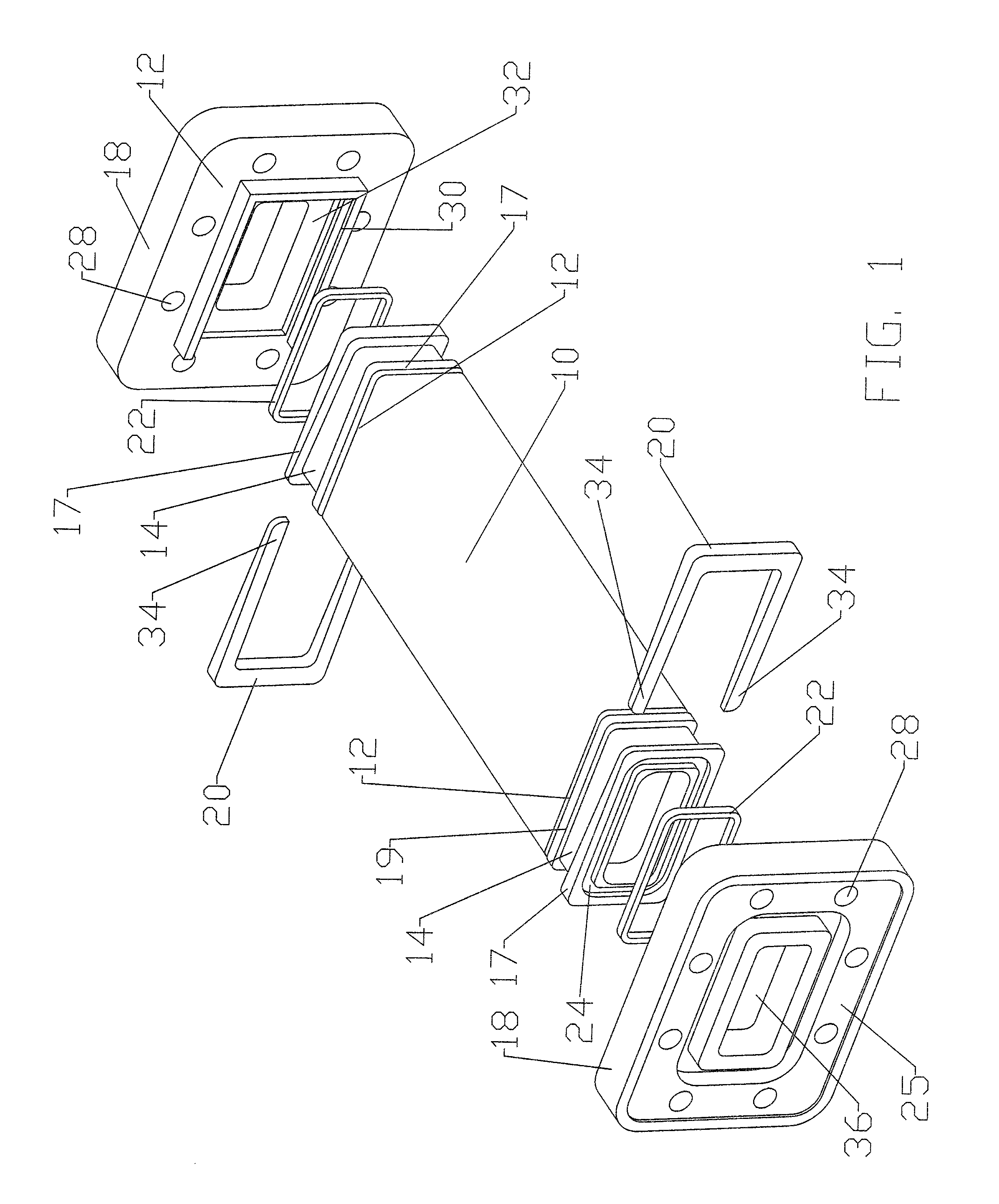
[0028] From the foregoing, one skilled in the art will appreciate that the invention provides a flange adaptor usable with a wide range of interfaces, whereby prior requirements for interface specific inventory are eliminated. Further, the complexity of and time requirements for final assembly operations are reduced, relative to prior solutions relying upon installation of multiple fasteners to achieve structural integrity of the flange adaptor to interface connection. Table of Parts10waveguide12waveguide end14flange adaptor16inner shoulder17outer shoulder18interface19sheath shoulder20retainer22gasket24recessed channel25interface end26extended waveguide portion28apertures30retaining groove32recessed area34leading edges36central passage

Problems solved by technology

Problems may occur at junctions between the waveguide and the selected interface(s), between the two mating interface surfaces of coupled waveguides and or between a waveguide and equipment connected thereto.
Possible issues that may be encountered include reflected power, high VSWR, power leakage and arcing.
The waveguides themselves are typically of standard dimensions, while an interface for coupling a standard waveguide to one manufacturer's equipment may not be adapted for coupling to the interface of another manufacturer's equipment.
Also, the plurality of fasteners and extra machining operations related to the fasteners themselves, the flange adaptor and the family of desired interface(s) creates a significant manufacturing, parts co-ordination and installation expense that reduces the inventory reduction savings resulting from its use.

Method used


Image

  • Universal waveguide interface adaptor
  • Universal waveguide interface adaptor
  • Universal waveguide interface adaptor

Examples


Embodiment Construction

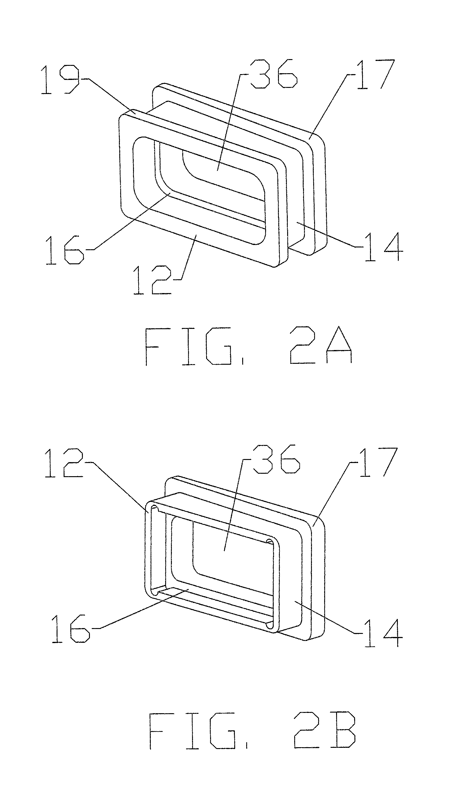
[0021] As shown in FIG. 1, each end of the waveguide 10 may be connected to the waveguide end 12 of a flange adaptor 14. At the waveguide end 12 of the flange adaptor 14, as shown in FIGS. 2A and 2B, a means for connection such as an inner shoulder 16 operates as a mounting region to receive the outer edges and surfaces of an end of the waveguide 10. A width of the inner shoulder 16 is adapted to the expected waveguide 10 wall thickness so that when the waveguide 10 end is seated in the inner shoulder 16 a flush interconnection is formed between a central passage of the waveguide 10 and a central passage 36 of the flange adaptor 14 that has the same cross-sectional dimension as the waveguide 10. As shown in FIGS. 1, 2A and 3A, the flange adaptor 14 may also have a sheath shoulder 19 for use with a flexible waveguide 10, or any other type of waveguide 10 with an outer sheath. The width of the sheath shoulder 19 is adapted to the expected thickness of the sheath and thus smoothes the ...


PUM


Abstract

A waveguide adaptor assembly with interface and waveguide ends for coupling an end of a waveguide with a desired interface configuration. The assembly including a flange adaptor adapted to receive the end of the waveguide. An outer shoulder projecting radially from the interface end of the flange adaptor is adapted to mate with a recessed area formed in the waveguide end of an interface. A pair of retaining groove(s) on opposing sides of the recessed area co-operating with each other and adapted to receive a retainer that, pressing upon a waveguide end of the outer shoulder as it is inserted, biases the interface end of the flange adaptor against the recessed area. The interface having the desired interface configuration at the interface end.

Description

BACKGROUND OF INVENTION [0001] 1. Field of the Invention [0002] This invention relates to waveguides and adaptations of waveguides to various interface components and more particularly to a method and apparatus for coupling a waveguide to any of a range of desired interfaces, for example a flange. [0003] 2. Description of Related Art [0004] Waveguides are commonly used for transmitting electromagnetic wave energy from one point to another. Waveguides are useful for the transmission of electromagnetic signals between, for example, antennas and transmitting or receiving equipment. Typically, the waveguide consists of a hollow metallic tube of defined cross-section, uniform in extent in the direction of propagation. Within the hollow tube, the electric and magnetic fields are confined. Waveguides may be either of a rigid wall or flexible variety and their cross-sectional shapes may be, for example, rectangular, circular, or elliptical. [0005] Waveguides are typically coupled to transmi...

Claims


Application Information

Patent Timeline
IPC IPC(8): H01P1/04
CPCH01P1/042
Inventor GRACZYK, FRANK J.GIACOBAZZI, JAMES
Owner ANDREW CORP
Learn More