Method, apparatus, and computer program product for radar detection of moving target

a technology of radar and moving target, applied in the field of detection of moving targets, can solve the problem of not enabling the determination of the speed of moving targets

Inactive Publication Date: 2005-12-29
THE BOEING CO
View PDF4 Cites 56 Cited by
  • Summary
  • Abstract
  • Description
  • Claims
  • Application Information

AI Technical Summary

Benefits of technology

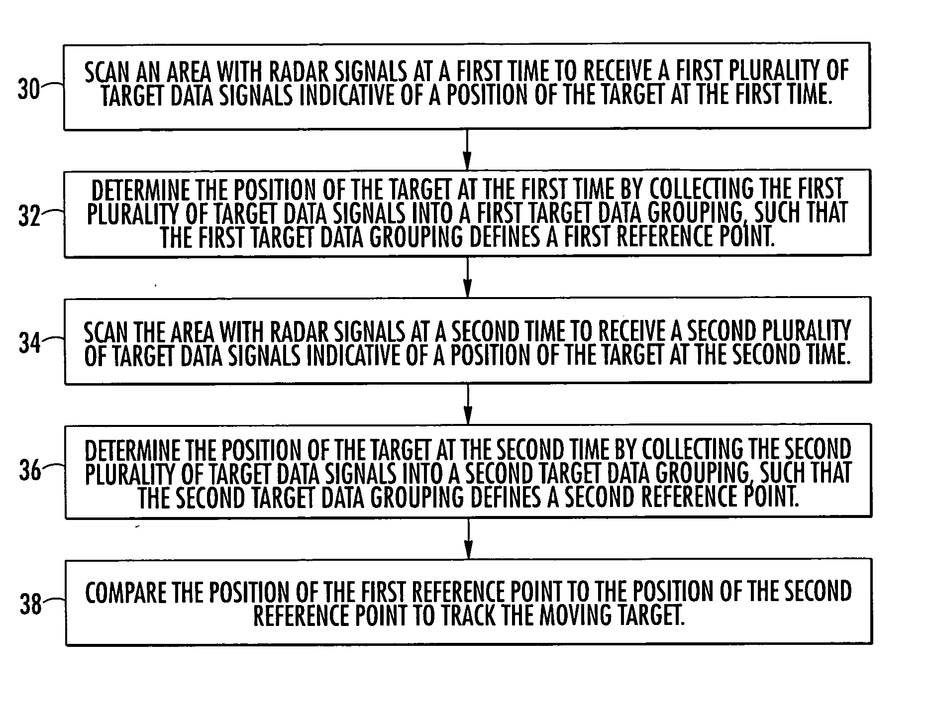
[0007] Methods, apparatus, and computer program products are provided according to the present invention for tracking a moving target, including a tangentially moving target, with a radar device without the use of Doppler information. In addition, the present invention provides for navigating an autonomous vehicle according to the tracked movement of the target. A moving target can be scanned at two different times so that target data signals returned from the target at the two times can be used to determine the location of the target at each time. By comparing the position of the target at the first and second times, the movement of the target can be tracked without the use of Doppler information. Furthermore, by tracking the moving target, an autonomous vehicle can be navigated relative to the moving target.
[0011] Therefore, embodiments of the present invention allow tracking of moving targets, including tangentially moving targets using a radar device without the use of Doppler information. Furthermore, embodiments of the present invention enable an autonomous vehicle to be navigated relative to a moving target without using Doppler information.

Problems solved by technology

Tangential movement of targets, relative to the rotating radar signal of the radar device, does not change the frequency of the signal and, accordingly, does not enable determination of the speed of the moving target.

Method used


Image

  • Method, apparatus, and computer program product for radar detection of moving target
  • Method, apparatus, and computer program product for radar detection of moving target
  • Method, apparatus, and computer program product for radar detection of moving target

Examples


Embodiment Construction

[0017] The present invention now will be described more fully hereinafter with reference to the accompanying drawings, in which some, but not all embodiments of the invention are shown. Indeed, the invention may be embodied in many different forms and should not be construed as limited to the embodiments set forth herein; rather, these embodiments are provided so that this disclosure will satisfy applicable legal requirements. Like numbers refer to like elements throughout.

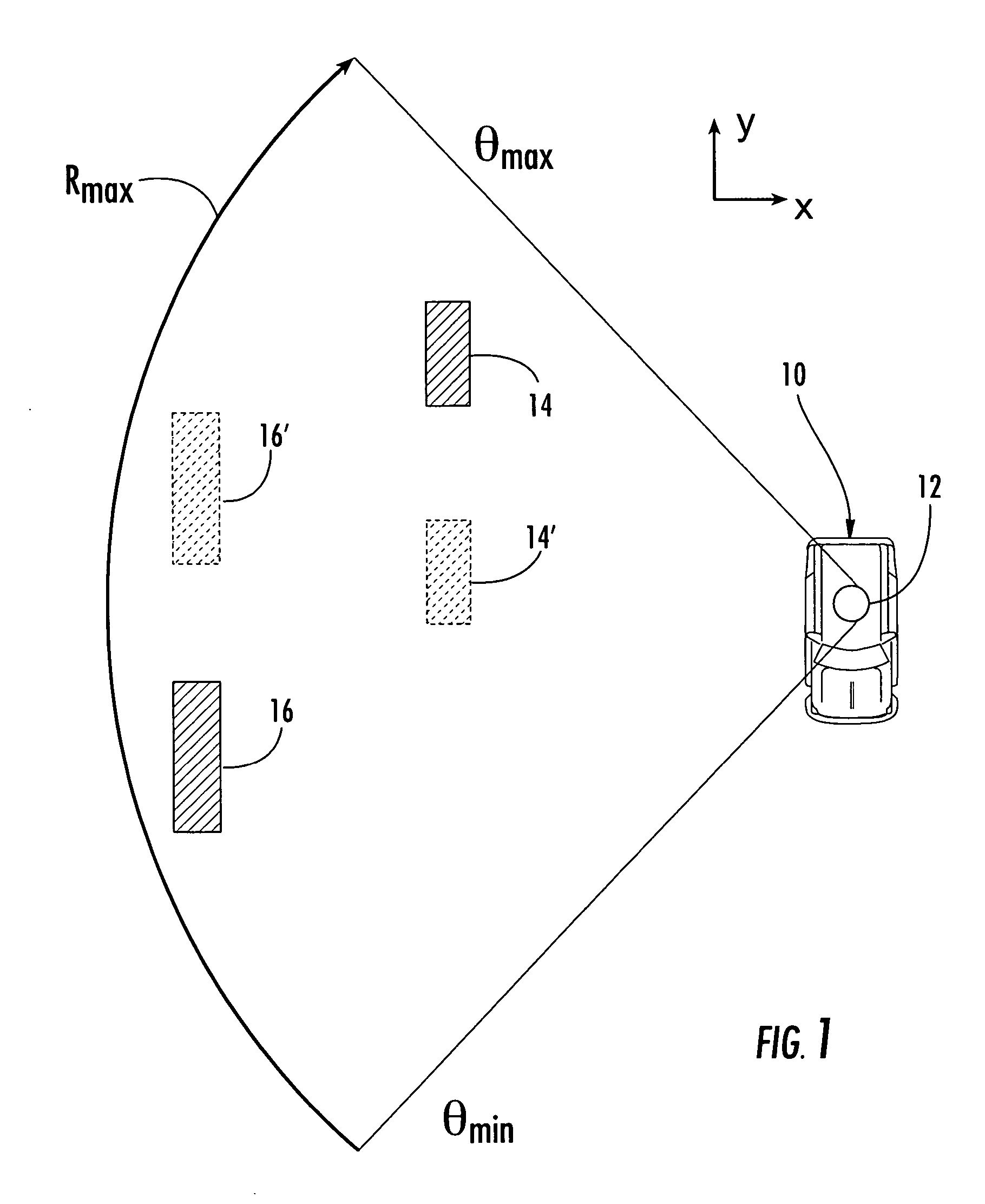
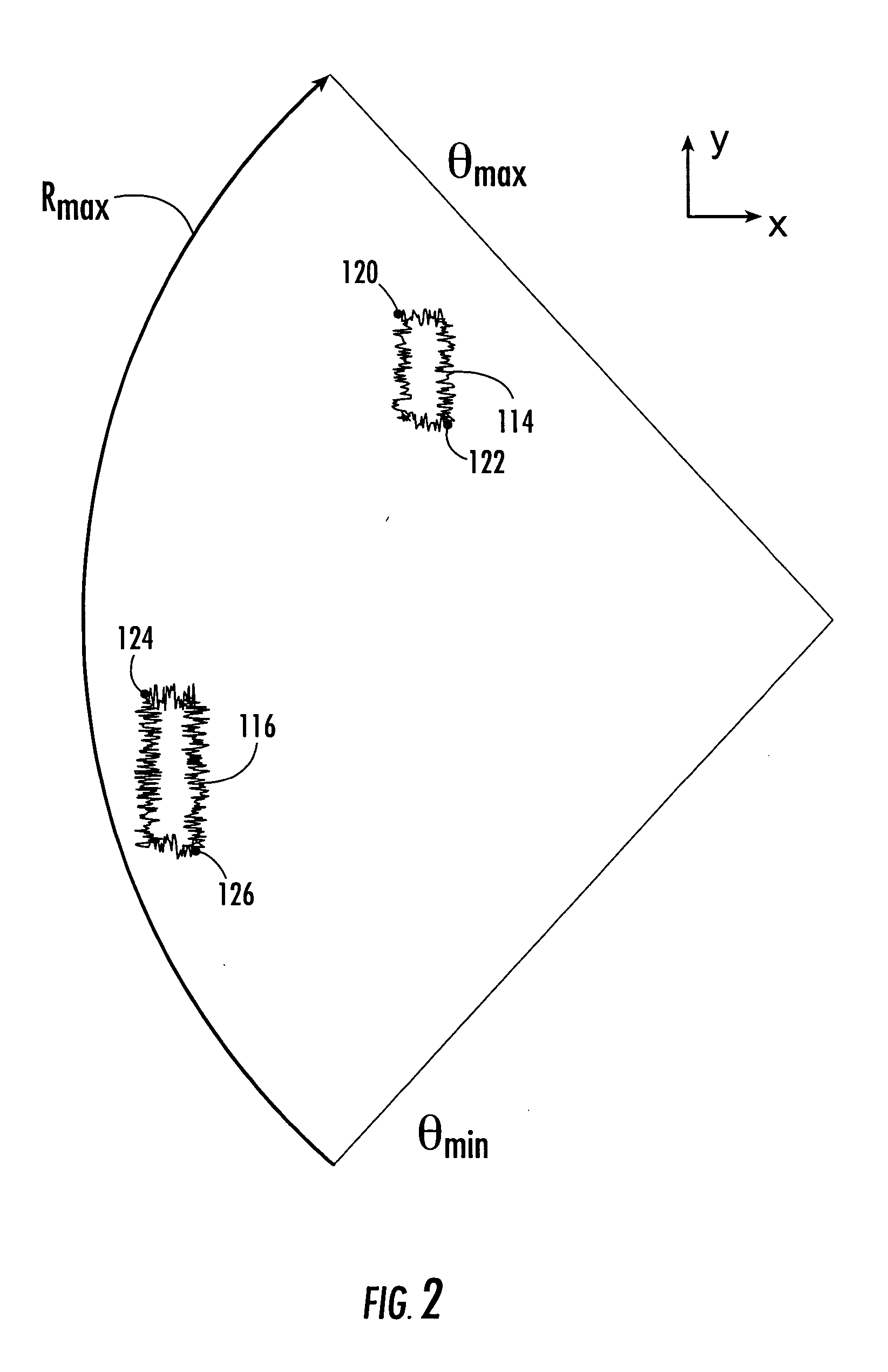
[0018] With reference to FIGS. 1-4, the tracking of at least one moving target without requiring the use of Doppler information in accordance with one embodiment of the methods, apparatus, and computer program products of the present invention is illustrated. Embodiments of the present invention provide for the tracking of moving targets with a radar device independent of Doppler information that may be provided by radar signals that are transmitted and received to determine the positions of the target. The embod...


PUM


Abstract

Methods, apparatus, and computer program products are provided for tracking at least one moving target with a radar device without requiring the use of Doppler information. The invention comprises scanning an area with radar signals at a first time to receive a first plurality of target data signals indicative of a position of the target at the first time and determining the position of the target at the first time by collecting the first plurality of target data signals into a first target data grouping, such that the first target data grouping defines a first reference point. Similarly, a second reference point for the target is determined for a second time, and the position of the first reference point is compared to the position of the second reference point to track the moving target. Advantageously, the tracked positions of the moving target may be used to predict a future position of the target at a subsequent time.

Description

BACKGROUND OF THE INVENTION [0001] 1. Field of the Invention [0002] The present invention is related to the detection of moving targets, and more particularly, to methods, apparatus, and computer program products for tracking a moving target without requiring the use of Doppler information. [0003] 2. Description of Related Art [0004] Radar devices, such as real beam radars, laser radars, sonar, and the like, transmit signals, such as electromagnetic or sonar signals, that advantageously reflect off targets and are received by the radar device to provide data related to the position of the target. Targets detected by radar devices may be stationary or moving objects. Radar devices typically comprise an antenna that transmits and receives the radar signals. Signals received by the radar device provide target data, such as the target's distance from the radar device or size. Some radar devices, such as a radar device used on an autonomous vehicle, typically rotate the antenna through 3...

Claims


Application Information

Patent Timeline
Patent Type & Authority Applications(United States)
IPC IPC(8): G01S13/66G01S13/72G01S13/93G01S15/66G01S17/66
CPCG01S13/726G01S17/66G01S15/66
Inventor WITTENBERG, PETER S.MOSHER, AARON Y.
Owner THE BOEING CO
Why Eureka
Try Eureka