
Liquid delivering device

a liquid delivery and liquid technology, applied in printing and other directions, can solve the problems of increasing power consumption at the time of ejection of ink, deteriorating the efficiency of piezoelectric actuator deformation, etc., and achieves the reduction of the rigidity of the piezoelectric actuator in the area surrounding the drive section, the effect of reducing the rigidity of the piezoelectric actuator

Active Publication Date: 2005-12-29
BROTHER KOGYO KK
View PDF9 Cites 21 Cited by
  • Summary
  • Abstract
  • Description
  • Claims
  • Application Information

AI Technical Summary

Benefits of technology

[0006] The present invention provides a liquid delivering device which enables efficient deformation of the piezoelectric layer and the diaphragm of the piezoelectric actuator.
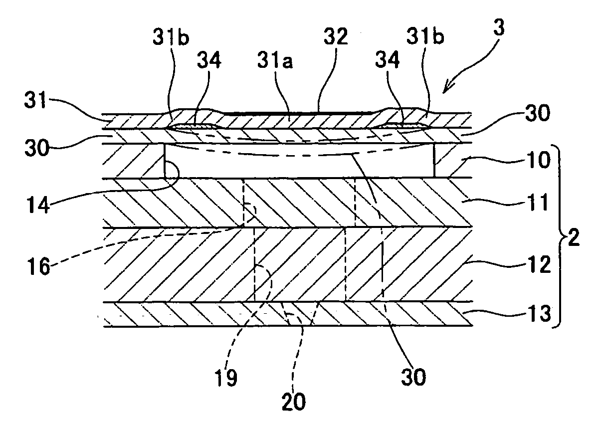
[0007] According to an aspect of the invention, there is provided a liquid delivering device including: a flow passage unit having a plurality of pressure chambers each of which communicating with a liquid ejection port; a piezoelectric actuator for selectively changing the volume of the plurality of pressure chambers, the piezoelectric actuator including a plurality of individual electrodes corresponding to the plurality of pressure chambers, a common electrode opposing the plurality of individual electrodes, and a piezoelectric layer sandwiched between the plurality of individual electrodes and the common electrode; and a rigidity reduction section which reduces the rigidity of the piezoelectric actuator and which is provided in an area where at least the pressure chamber is formed and in a vicinity of the individual electrode, in perspective plan view.
[0009] A rigidity reduction section is provided in an area (i.e., an area surrounding the drive section) where the pressure chamber is formed and in the vicinity of the individual electrode when viewed in a direction orthogonal to a plane where the pressure chambers are provided. The rigidity of the piezoelectric actuator in the area surrounding the drive section is partially decreased by means of the rigidity reduction section. When the piezoelectric layer of the drive section has been deformed through extension and contraction, the piezoelectric layer and the diaphragm in the area opposing the pressure chamber become easy to deform in association with such deformation, thereby enabling efficient deformation of the piezoelectric actuator at a low voltage.

Problems solved by technology

However, if the piezoelectric layer is formed to a uniform thickness continuously across the plurality of pressure chambers, the rigidity of the piezoelectric actuator in the area opposing the pressure chambers (particularly, the area surrounding the drive section) becomes high, and the piezoelectric layer and the diaphragm of the entire area opposing the pressure chambers become less susceptible to deformation, thereby deteriorating the efficiency of deformation of the piezoelectric actuator.
For this reason, there is a necessity for applying a high voltage to individual electrodes to thereby apply pressure to the ink in the pressure chambers, leading to an increase in power consumption at the time of ejection of ink.

Method used


Image

  • Liquid delivering device
  • Liquid delivering device
  • Liquid delivering device

Examples


Embodiment Construction

[0031] An embodiment of the present invention will be described. The present embodiment is an example in which the present invention is applied to a piezoelectric actuator used in an inkjet head.

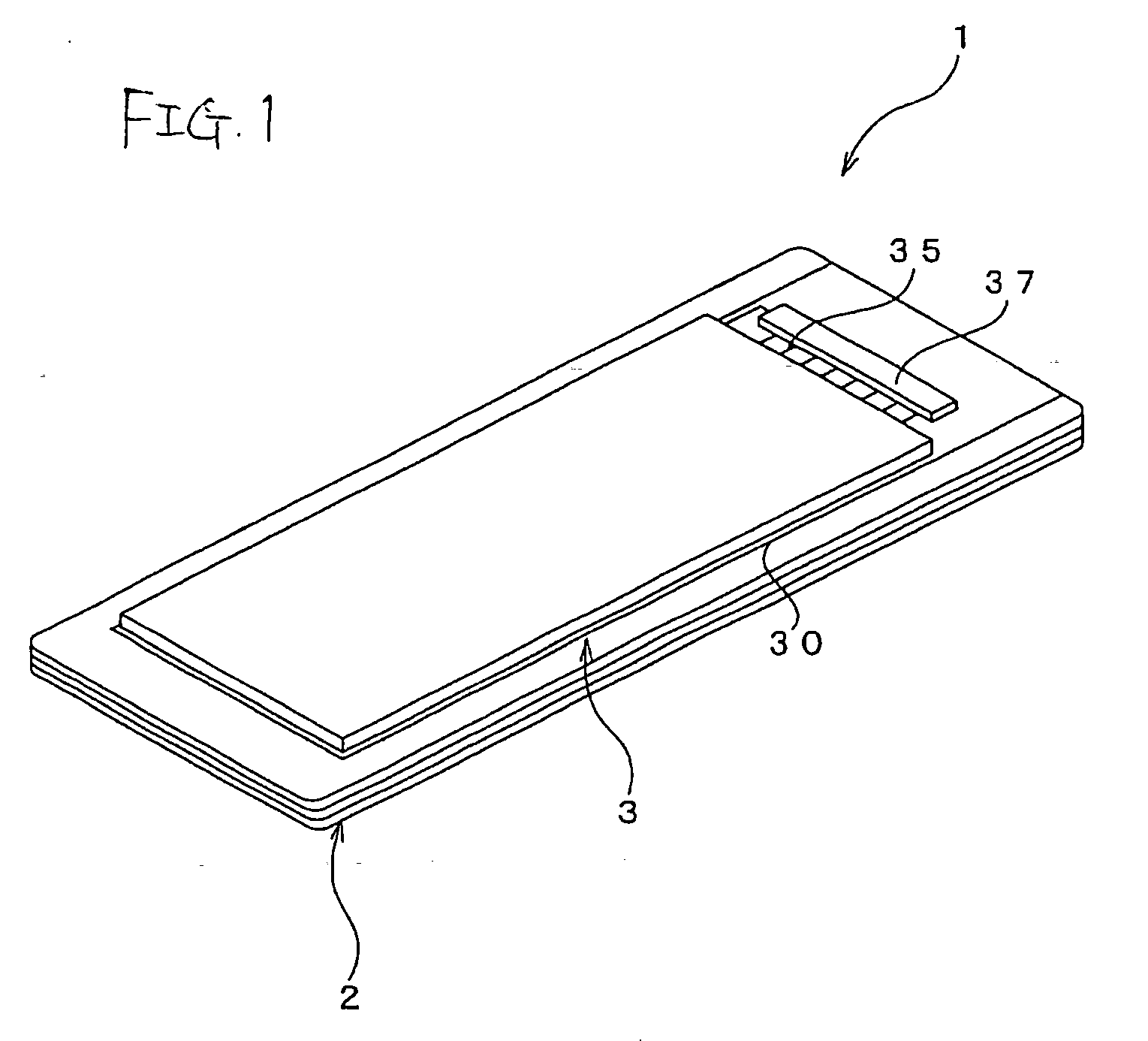
[0032] As shown in FIG. 1, an inkjet head 1 has a flow passage unit 2 in which ink flow passages are formed, and a piezoelectric actuator 3 stacked on an upper surface of the flow passage unit 2.

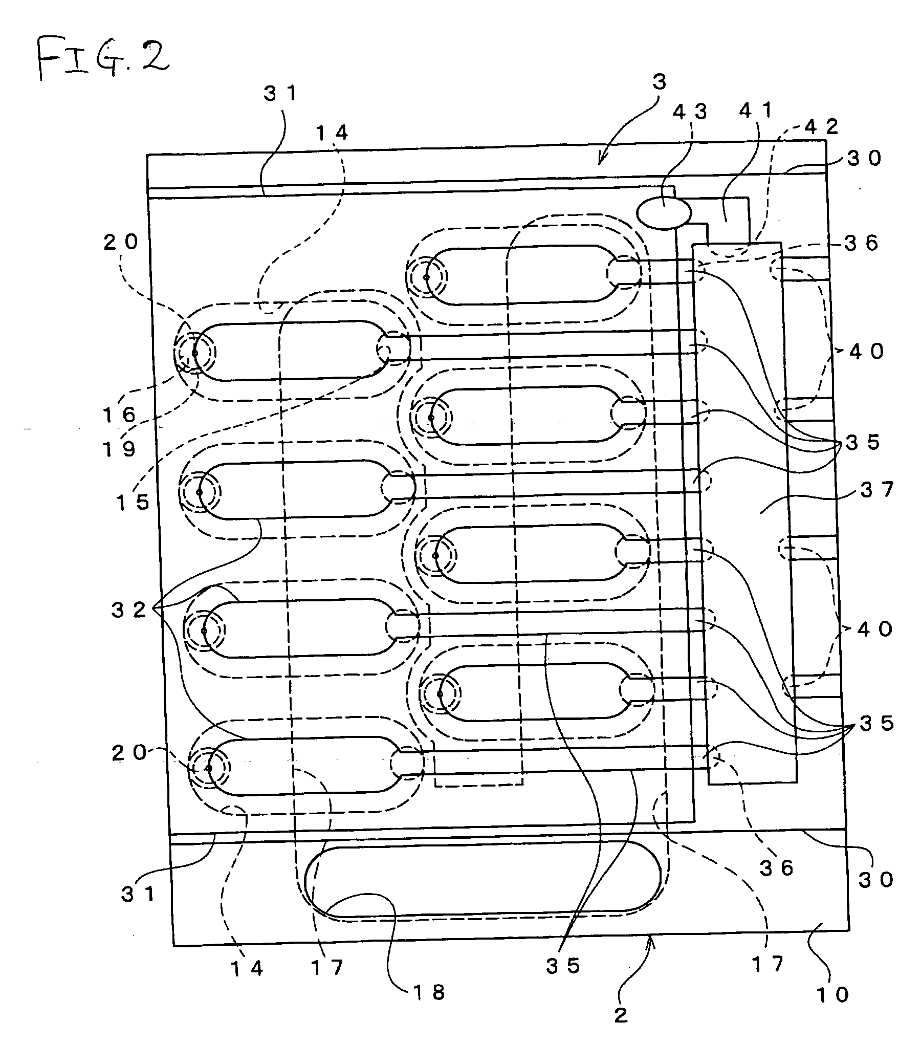
[0033] First, the flow passage unit 2 will be described. FIG. 2 is a schematic plan view of a right-side portion of the inkjet head 1 shown in FIG. 1. FIG. 3 is a fragmentary enlarged view of FIG. 2; FIG. 4 is a cross-sectional view taken along line IV-IV shown in FIG. 3; and FIG. 5 is a cross-sectional view taken along line V-V shown in FIG. 3. As shown in FIGS. 2 to 4, the flow passage unit 2 has a cavity plate 10, a base plate 11, a manifold plate 12, and a nozzle plate 13. These four plates 10 to 13 are bonded together in a stacked manner. Of these plates, the cavity plate 10, the base plate 11...


PUM


Abstract

A liquid delivering device including: a flow passage unit having a plurality of pressure chambers each of which communicating with a liquid ejection port; a piezoelectric actuator for selectively changing the volume of the plurality of pressure chambers, the piezoelectric actuator including a plurality of individual electrodes corresponding to the plurality of pressure chambers, a common electrode opposing the plurality of individual electrodes, and a piezoelectric layer sandwiched between the plurality of individual electrodes and the common electrode; and a rigidity reduction section which reduces the rigidity of the piezoelectric actuator and which is provided in an area where at least the pressure chamber is formed and in a vicinity of the individual electrode, in perspective plan view.

Description

BACKGROUND OF THE INVENTION [0001] 1. Field of the Invention [0002] The present invention relates to a liquid delivering device such as an inkjet head which effects recording on a recording medium by means of ejecting ink on the same. [0003] 2. Description of the Related Art [0004] An inkjet head, which has hitherto been known, has a piezoelectric actuator which deforms a piezoelectric layer by subjecting the piezoelectric layer to an electric field, and ink is ejected by application of pressure, by means of the piezoelectric actuator, to the ink stored in a pressure chamber (see JP-A-11-334087 (see FIG. 3)). The inkjet head piezoelectric actuator disclosed in JP-A-11-334087 is a unimolf-type piezoelectric actuator including a diaphragm which also functions as a lower electrode (a common electrode); a piezoelectric layer formed from lead zirconate titanate (PZT) or the like made on the surface of the diaphragm; and a plurality of upper electrodes (individual electrodes) formed on th...

Claims


Application Information

Patent Timeline
Patent Type & Authority Applications(United States)
IPC IPC(8): B41J2/045B41J2/14
CPCB41J2/14233B41J2002/14491B41J2002/14459B41J2002/14266
Inventor SUGAHARA, HIROTO
Owner BROTHER KOGYO KK
Learn More