
Circuit interrupting device with a single test-reset button

a circuit interrupting device and reset button technology, applied in the field of resettable circuit interrupting devices, can solve the problems of improper connection to electrical power, no power is available to any user accessible receptacle, and the user cannot access the electric power of such devices, so as to achieve the effect of simplifying the operation of the devi

Active Publication Date: 2005-12-29
LEVITON MFG
View PDF99 Cites 13 Cited by
  • Summary
  • Abstract
  • Description
  • Claims
  • Application Information

AI Technical Summary

Benefits of technology

[0014] The devices of the present invention each further has a pair of movable bridges which are electrically connected to the line terminals. The movable bridges electrically connect the line terminals to the load and face terminals when the devices are reset thus bringing power to the face of the devices. The movable bridges are mechanically biased away from the load and face terminals. When the devices are improperly wired or reverse wired (i.e., power connected to load terminals), the reset lockout mechanism prevents the movable bridges from connecting the line terminals to the load and face terminals even when an attempt is made to reset the device thus preventing electric power to be present at the face terminals or user accessible plugs and / or receptacles.
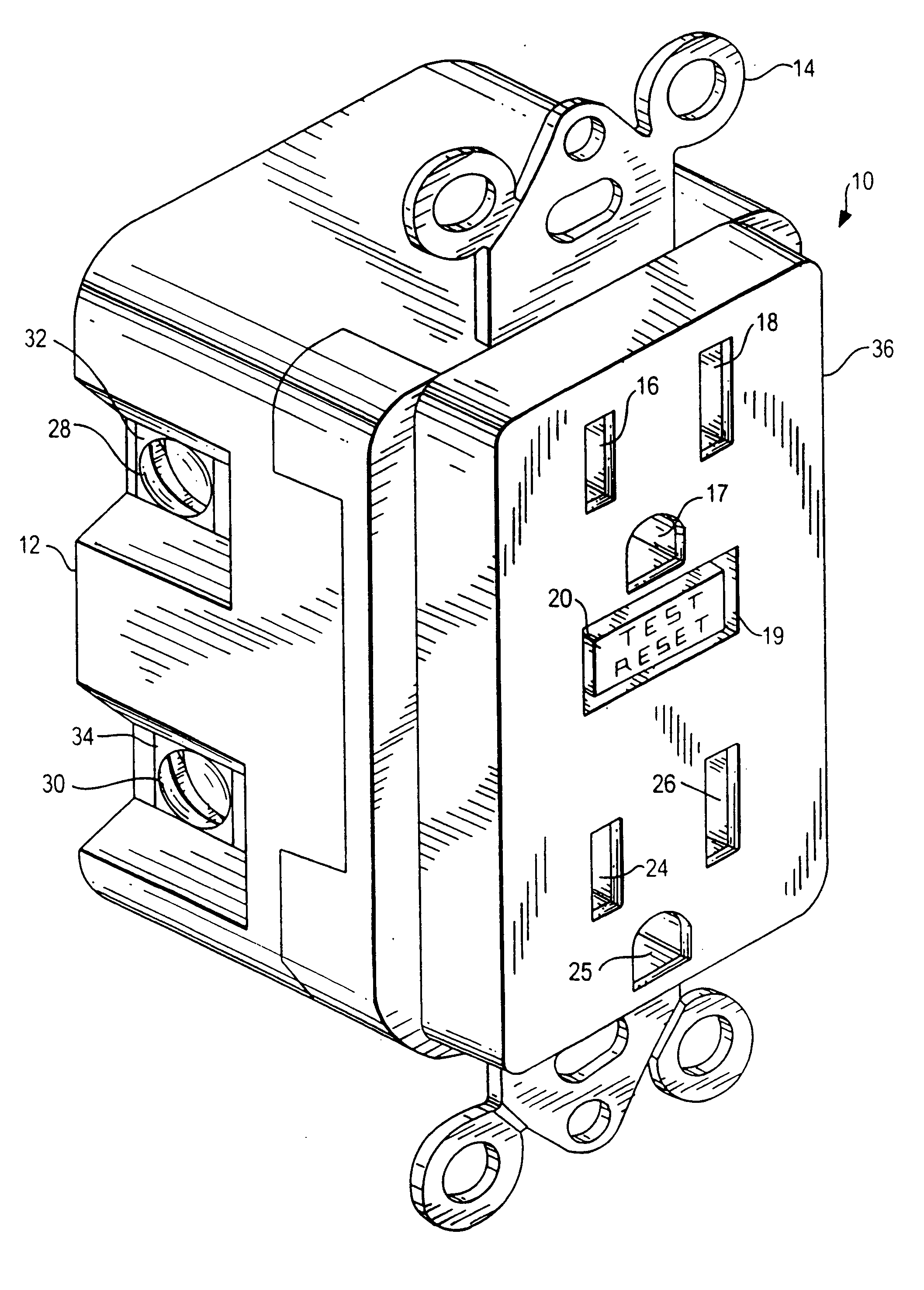
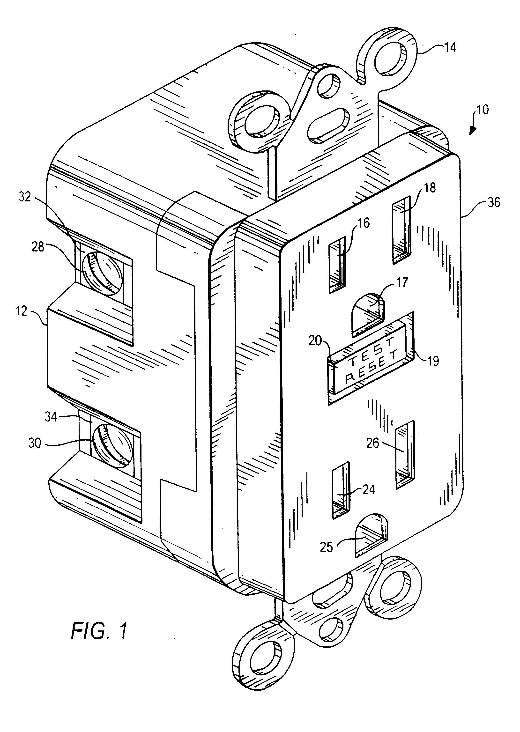
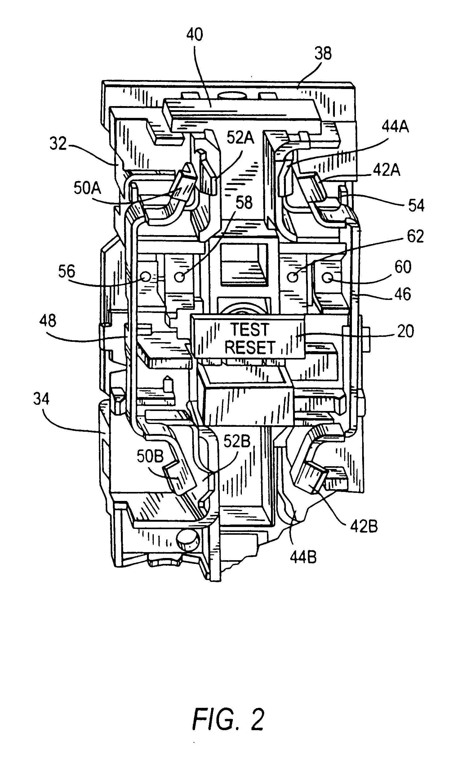
[0015] In one embodiment, the present application is directed to circuit interrupting devices that include a single test-reset button for triggering a reset portion and a circuit interrupting portion. The reset portion includes functionality to make electrically conductive paths between a line side and a load side of a device. The circuit interrupting portion includes functionality to break electrically conductive paths between the line side and load side. In particular, the circuit interrupting portion is an electro-mechanical mechanism that comprises a coil and plunger assembly, a latch plate and lifter assembly, a mechanical switch assembly and a mechanical trip actuator assembly. The circuit interrupting portion is capable of automatically tripping or breaking electrical connections between the load and line side upon detection of a fault or a predetermined condition. The circuit interrupting portion also can manually break electrical connections by using only the mechanical portion of the circuit interrupting portion using the test-reset button, the latch plate and lifter assembly and the mechanical trip actuator. The reset portion comprises common components as the circuit interrupting portion, particularly the same test-reset button. As a result, the operation of the device is simplified.
[0016] One embodiment for the circuit interrupting device uses an electro-mechanical circuit interrupting portion that causes electrical discontinuity between the line, load and face terminals. A reset lockout mechanism prevents the reestablishing of electrical continuity between the line, load and face terminals unless the circuit interrupting portion is operating properly. That is, the reset lockout prevents resetting of the device unless the circuit interrupting portion is operating properly. The reset portion allows the device to be reset causing electrical continuity between the line terminals and the load terminals and electrical continuity between the line terminals and the face terminals; i.e., device in reset mode. Also, there is electrical continuity between the load terminals and the face terminals when the device is reset. Thus the reset portion establishes electrical continuity between the line, load and face terminals. The electromechanical circuit interrupting portion comprises a latch plate and lifter assembly, a coil and plunger assembly, a mechanical switch assembly, the movable bridges, a mechanical trip actuator and the sensing circuit.

Problems solved by technology

The devices prevent electric power from being accessible to users of such devices when these devices are reversed wired.
When the devices are not reset and if such devices are reverse wired no power is available to any user accessible receptacles and / or plugs located on the face of the devices.
The load terminals are capable of being electrically connected to a load and are improperly connected to electrical power when the device is reverse wired.

Method used


Image

  • Circuit interrupting device with a single test-reset button
  • Circuit interrupting device with a single test-reset button
  • Circuit interrupting device with a single test-reset button

Examples


Embodiment Construction

[0030] The present application contemplates various types of circuit interrupting devices that have at least one conductive path. The conductive path is typically divided between a line side that connects to electrical power, a load side that connects to one or more loads and a user side that connects to user accessible plugs or receptacles. As noted, the various devices in the family of resettable circuit interrupting devices comprise: ground fault circuit interrupters (GFCI's), arc fault circuit interrupters (AFCI's), immersion detection circuit interrupters (IDCI's), appliance leakage circuit interrupters (ALCI's) and equipment leakage circuit interrupters (ELCI's).

[0031] For the purpose of the present application, the structure or mechanisms used in the circuit interrupting devices, shown in the drawings and described hereinbelow, are incorporated into a GFCI device suitable for installation in a single-gang junction box used in, for example, a residential electrical wiring sys...


PUM


Abstract

A ground fault circuit interrupter device having a single actuator for sequentially activating a circuit interrupting portion when the device is in a reset condition and a reset portion when the device is in a tripped condition. The circuit interrupting portion breaks a conductive path between a line terminal and load terminal upon the occurrence of a predetermined condition thereby placing the device in the tripped condition and the reset portion reestablishes the conductive path between the line terminal and the load terminal thereby placing the device in the reset condition.

Description

[0001] This application claims the benefit of the filing date of a provisional application having Ser. No. 60 / 560,446 which was filed on Apr. 8, 2004.BACKGROUND OF THE INVENTION [0002] 1. Field of the Invention [0003] The present application is directed to a family of resettable circuit interrupting devices and systems that comprises ground fault circuit interrupters (GFCI's), arc fault circuit interrupters (AFCI's), immersion detection circuit interrupters (IDCI's), appliance leakage circuit interrupters (ALCI's), equipment leakage circuit interrupters (ELCI's), circuit breakers, contactors, latching relays and solenoid mechanisms. More particularly, the present application is directed to circuit interrupting devices having a single actuator for breaking and making electrically conductive paths between a line side and a load side of the devices. [0004] 2. Description of the Related Art [0005] Many electrical wiring devices have a line side, which is connectable to an electrical pow...

Claims


Application Information

Patent Timeline
Patent Type & Authority Applications(United States)
IPC IPC(8): H01H83/04H02H3/00
CPCH01H83/04
Inventor GERMAIN, FRANTZ
Owner LEVITON MFG
Learn More