Remote control wiring mechanism

Inactive Publication Date: 2005-12-29
MATSUSHITA ELECTRIC WORKS LTD
View PDF3 Cites 9 Cited by
  • Summary
  • Abstract
  • Description
  • Claims
  • Application Information

AI Technical Summary

Benefits of technology

[0016] The present invention is contrived to solve the above-mentioned problems and it is an object of the present invention to provide a remote contr

Problems solved by technology

As described above, since the transmission unit 10, the monitoring unit 11, the control unit 12, the relay 14, and the remote control transformer 16 are required for constructing the remote monitoring and control system, there are problems that the number of constituent elements is large and that the work of selecting the elements at the time

Method used


Image

  • Remote control wiring mechanism
  • Remote control wiring mechanism
  • Remote control wiring mechanism

Examples


Example

First Embodiment

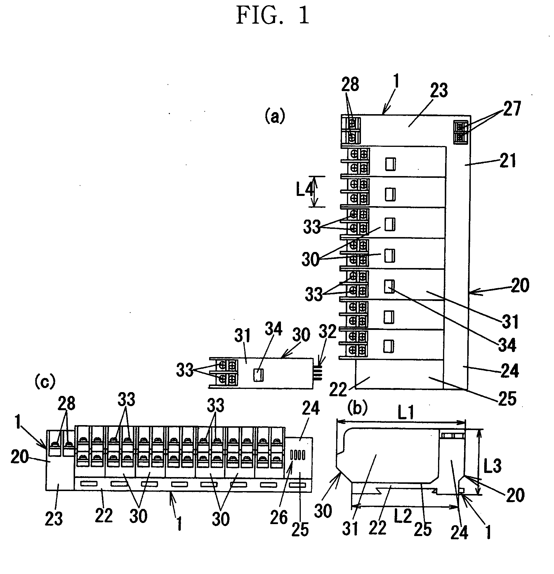
[0047] In the mother device 1 constructing the system shown in FIG. 5, a body 21 of a main unit 20 has a shape that a side frame 23 is protruded from one side of two sides adjacent to each other in a rectangular bottom plate 22 and a rear frame 24 is protruded from the other side, as shown in FIG. 1. The side frame 23 and the rear frame 24 have the same height from the bottom plate 22 and the side frame 23 and the rear frame 24 meet each other at one corner of the bottom plate 22. In brief, since the side frame 23 and the rear frame 24 meet each other, it is formed in an L shape as seen in a plan view. The portion surrounded with the bottom plate 22, the side frame 23, and the rear frame 24 serves as a relay support platform 25 in which the relay units 30 are disposed.

[0048] The number of the relay units 30 arranged in the relay support platform 25 is eight in maximum. That is, as shown in FIG. 1(c), eight relay sockets 26 as eight relay fitting parts are formed on...

Example

Second Embodiment

[0064] The present embodiment is obtained by modifying the structure of the first embodiment and as shown in FIG. 6, the main unit 20 comprises a power supply unit 20a not built with the relay driving circuit 44 but built with the power supply circuit 41 and socket units 20b not built with the power supply circuit 41 but built with the relay driving circuit 44 and the relay sockets 26, where the power supply unit 20a and the socket units 20b are successively disposed. Each socket unit 20b has one relay socket unit 26 and eight socket units 20b in maximum can be successively disposed. That is, the power supply unit 20a is formed in a rectangular parallelepiped shape corresponding to the side frame 23 in the main unit 20 of the first embodiment. The socket units 20b have a width (size L4 of FIG. 1) suitable for fitting one relay unit 30 thereto and has a bottom plate 22 and a rear frame 24. In other words, the power supply unit 20a has a unit size in the agreed switc...

Example

Third Embodiment

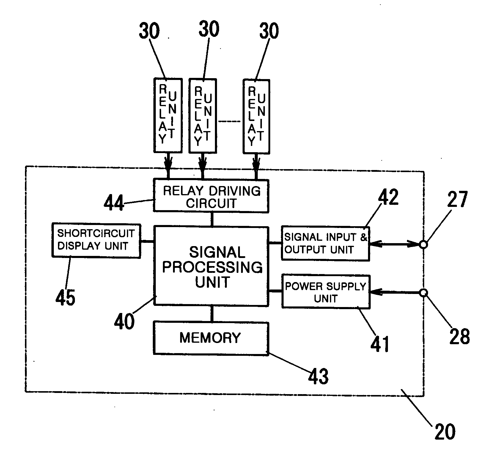
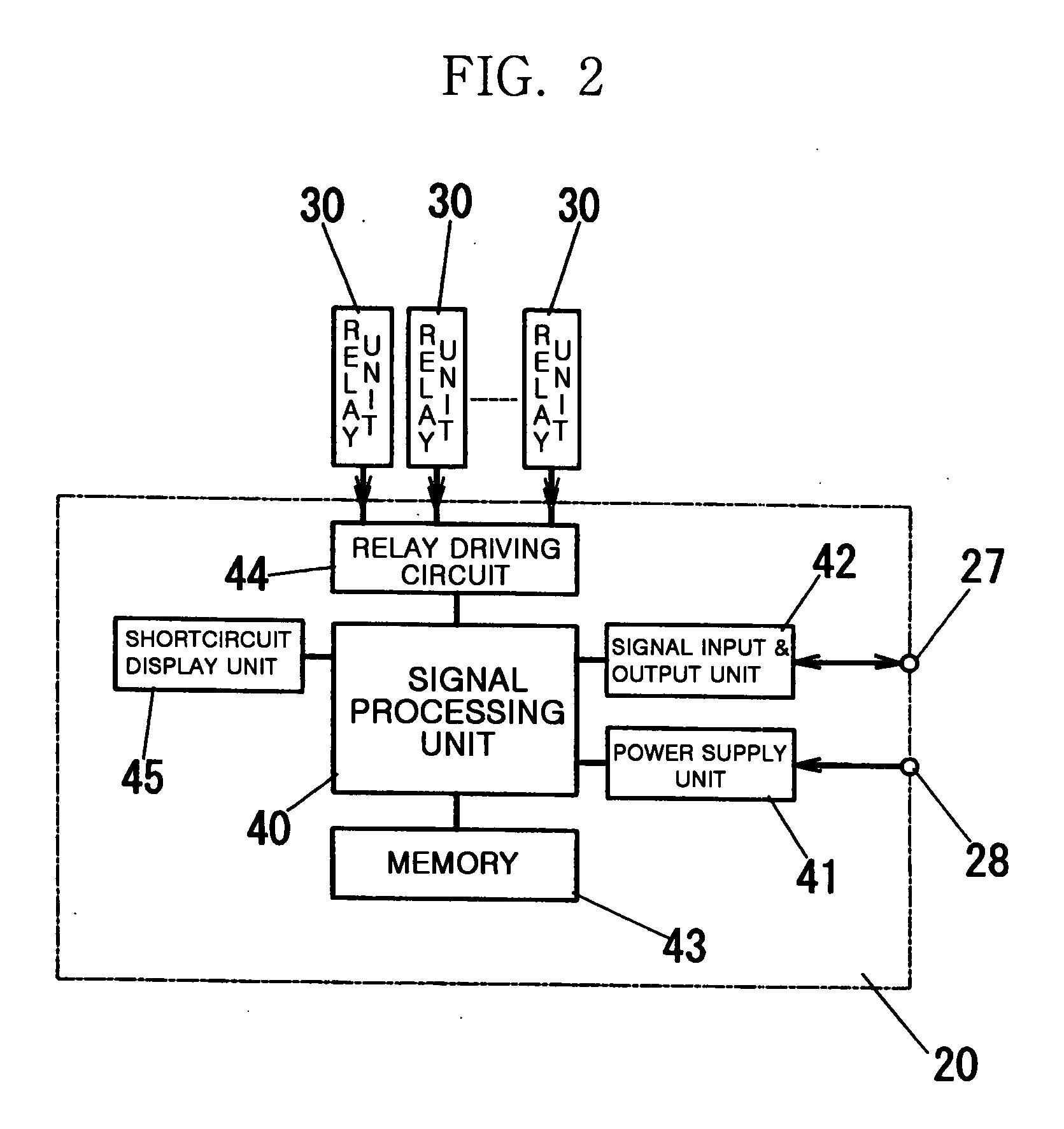
[0074] In the embodiments described above, the mother device 1 is supplied with the commercial power. However, in the present embodiment, the mother device 1 is supplied with power obtained by stepping down the commercial power with a step-down transformer such as a remote control transformer. That is, since a difference between input voltage and output voltage of the power supply circuit 41 provided in the mother device 1 is small, the size of the power supply circuit 41 can be reduced and the insulating countermeasure for the internal circuits is simplified. Therefore, in the present embodiment, as shown in FIG. 9, the main unit 20 having a shape that the side frame 23 is removed from the main unit 20 described in the first embodiment is used. In brief, the power supply unit 41 is built in the rear frame 24 of the main unit 20. The power supply terminals 27 and the signal terminals 28 have terminal screws and are disposed apart from each other at the ends of the r...


PUM


Abstract

There is provided a remote control wiring mechanism, which makes it easy to construct a system by facilitating a connection work and treatment of members constructing the system. A main unit 20 comprises signal terminals 27 connected to signal lines and power supply terminals 28 for supply power used for driving a relay. A relay unit 30 having a relay is detachably connected to a relay socket 26 of the main unit 20 and is coupled integrally to the main unit 20. When a transmission signal including on-off information of a switch is received through the signal lines, the on-off state of the switch is reflected in the switching of the relay.

Description

BACKGROUND OF THE INVENTION [0001] 1. Field of the Invention [0002] The present invention relates to a remote control wiring mechanism in which an on-off state of a switch is reflected in the switching of a relay by transmitting a transmission signal including on-off information of the switch through a signal line. [0003] 2. Description of the Related Art [0004] Conventionally, in order to remotely monitor and control loads, there is known a technology of transmitting a transmission signal including on-off information of a switch through a signal line and switching a relay for turning on and off a load power in accordance with the transmission signal. The switch includes automatic switches for outputting a contact signal corresponding to sensed results of various sensors, as well as switches manipulated by persons. [0005] As such a type of remote monitoring and control system, there is a known a central control system having a monitoring unit 11 having switches 13 and a control unit...

Claims


Application Information

Patent Timeline
IPC IPC(8): G08C19/16H01H47/22H01H50/04H01H73/00H05B37/02
CPCH01H50/048H05B37/0254H05B37/02H05B47/165H05B47/17H05B47/18G05B19/02G05B23/02
Inventor HATEMATA, TAKESHI
Owner MATSUSHITA ELECTRIC WORKS LTD
Why Eureka
Try Eureka