
Optical reading apparatus, character recognition processing apparatus, character reading method and program, magnetic ink character reading apparatus, and POS terminal apparatus

a technology of character recognition and reading apparatus, applied in the direction of character and pattern recognition, instruments, computing, etc., can solve the problems of increasing the time more time is required for the reading process, etc., and achieve the effect of improving the mismatch rate and improving the correct recognition ra

Inactive Publication Date: 2005-12-29
SEIKO EPSON CORP
View PDF4 Cites 34 Cited by
  • Summary
  • Abstract
  • Description
  • Claims
  • Application Information

AI Technical Summary

Benefits of technology

[0009] An object of the present invention is therefore to provide an optical reading apparatus, optical character recognition processing apparatus, character reading method and program that is capable of reducing the time it takes to read and recognize a string of characters on a processed medium. The invention achieves this by selectively using a broad recognition area that allows for variation in character positions and a narrower recognition area in which the probability of the desired character string being present is high depending on past results. The optical reading apparatus may be embodied in a magnetic character reading apparatus that may be further embodied in a POS terminal apparatus, and the optical reading and recognition method may be operated in conjunction with a magnetic reading and recognition method.
[0013] Thus, the size of the matching area that is processed next for character recognition is based on the position of the character recognized by the optical character recognition unit in the previous matching area. In order to reliably read the characters, each matching area must be large enough to account for variations in the printing positions of the characters, variation in the dimensions of the processed medium, and variations in the dimensions of the reading apparatus. On the other hand, adjacent characters usually deviate very little from the specified standard character positions. Therefore, setting the next matching area based on the position of the just-recognized character justifiably enables setting that matching area to a narrow width that still provides sufficient tolerance for offset variations that might occur between adjacent characters. The range to which the recognition process is applied is therefore narrower, and the time required to run the recognition process can be reduced.
[0015] The width of the matching area set in the direction perpendicular to the base line of the character string is thus the width of the template in the same direction when the template is positioned at the location of the recognized character plus a specific correction margin. Adjacent characters usually deviate very little from the specified standard character positions, and the likelihood that the next character is located within the width of the template in the direction perpendicular to the base line of the character string when the template is aligned at the position of the recognized character is therefore high. Furthermore, by adding a specific margin to this width to allow for the slight deviation that might occur between the positions of adjacent characters, the likelihood that the next character will be in the matching area is even higher. The likelihood that the optical character recognition unit can recognize the next character can be increased as a result of the matching area determination unit thus setting the width of the matching area in the direction perpendicular to the base line of the character string to the width of the template in the direction perpendicular to the base line of the character string when the template is positioned at the location of the recognized character plus a specific correction margin.
[0021] Therefore, if the area in which character recognition is not possible continues for more than a specified distance, re-applying the recognition process to the full width of the image increases the likelihood that the characters in the intended recognition target located at a position separated from the mistakenly recognized noise character can be recognized.
[0024] The MICR apparatus of this aspect of the invention thus has an optical reading apparatus that can suppress any increase in the time required for the character recognition process during optical character recognition, and can thus suppress an increase in the time required for the MICR apparatus to run the magnetic ink character recognition process.
[0026] A POS terminal according to another aspect of the present invention has a magnetic ink character reading apparatus as described above. When MICR and OCR results do not match because of an OCR error when processing checks at a POS terminal, for example, this aspect of the invention enables improving the mismatch rate and thus improving the correct recognition rate.

Problems solved by technology

If the magnetic ink characters are incorrectly recognized, transaction processing will proceed based on incorrect data, potentially resulting in major post-processing problems such as the wrong account, that is, an account other than the account on which the check is actually drawn, being debited for payment.
A problem with adding a process for reading characters using an optical reading apparatus is that more time is required for the reading process.
Applying the character recognition process to a larger area, however, necessarily increases the time required to perform the process.

Method used


Image

  • Optical reading apparatus, character recognition processing apparatus, character reading method and program, magnetic ink character reading apparatus, and POS terminal apparatus
  • Optical reading apparatus, character recognition processing apparatus, character reading method and program, magnetic ink character reading apparatus, and POS terminal apparatus
  • Optical reading apparatus, character recognition processing apparatus, character reading method and program, magnetic ink character reading apparatus, and POS terminal apparatus

Examples


Embodiment Construction

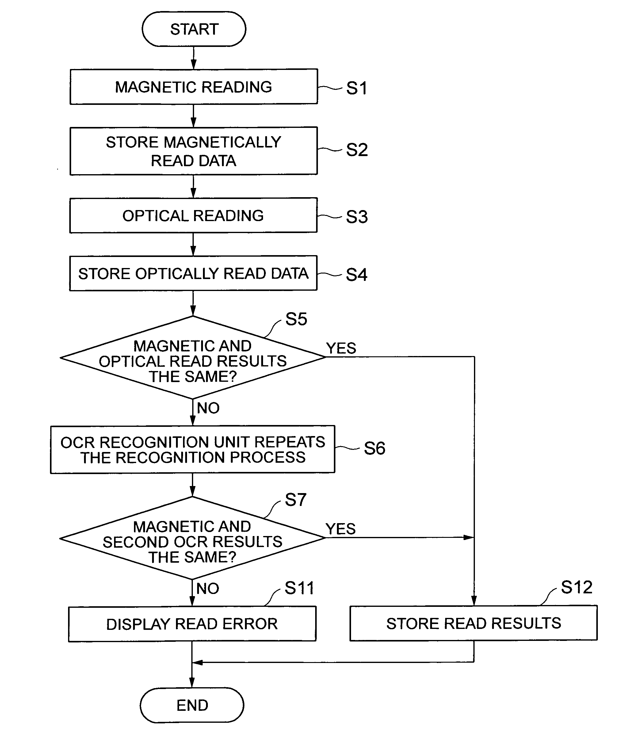
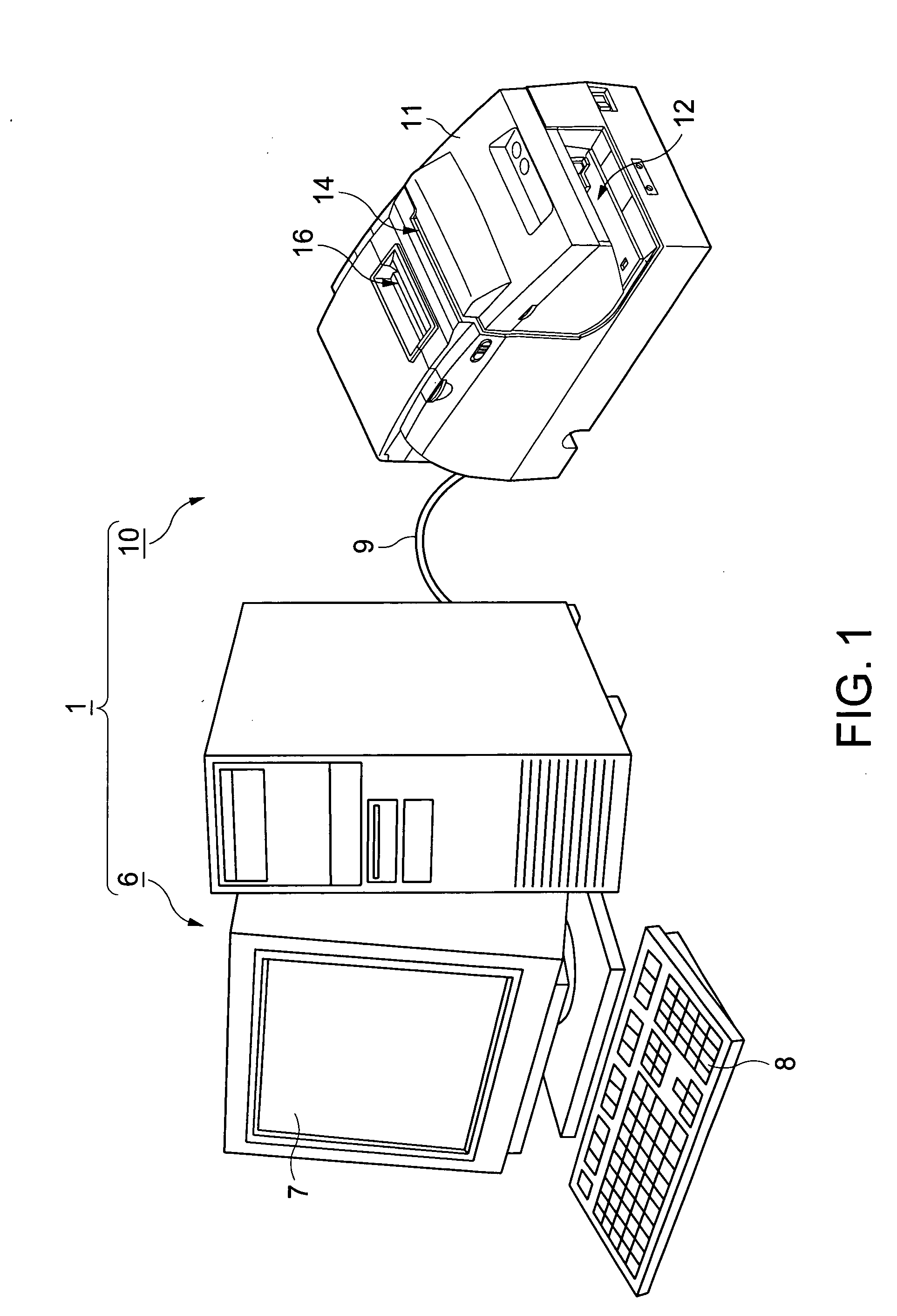
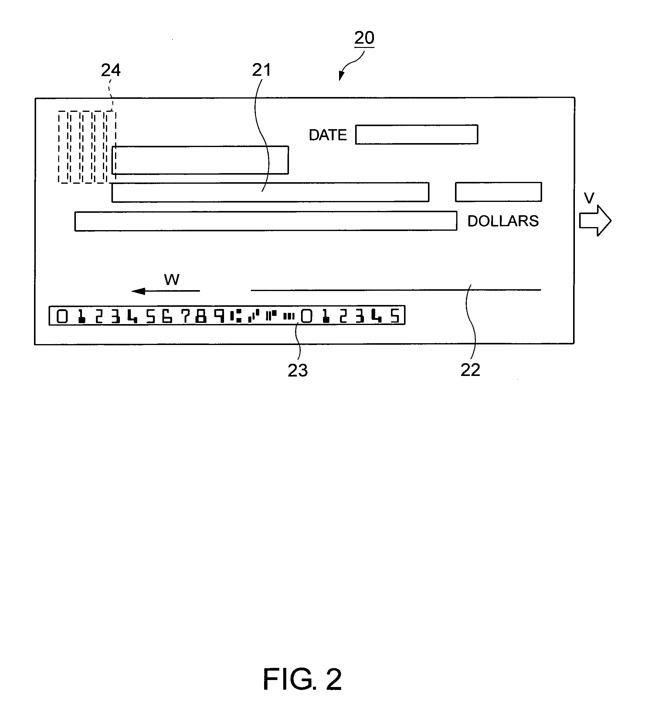
[0036] Preferred embodiments of an optical reading apparatus according to the present invention are described below with reference to the accompanying figures. FIG. 1 is an oblique view of a host apparatus and a hybrid apparatus having the capability to both magnetically and optically read magnetic ink characters according to embodiments of the invention. FIG. 2 is a plan view showing, by way of example, the face of a check as a processed medium. To complete a check transaction, the front of the check is filled out, including the payment amount and signature, check validity is confirmed, and the check is endorsed. By providing a magnetic ink character reading apparatus in a printer, as embodiments of this invention do, the entire check processing operation including reading the magnetic ink characters and printing information on the front and back of the check used in the transaction can be executed by a single machine.

[0037] The present invention relates to an apparatus and a meth...


PUM


Abstract

An optical reading apparatus and optical character recognition processing apparatus operating in conjunction with a magnetic ink character reading apparatus reduce the time in reading a string of characters formed in a line on a processed medium. This is done in the optical reading and recognition operations by selectively using a broad recognition area that allows for variation in character positions and a narrower recognition area where the probability of the desired character string being present is high depending on past results. An extracted image containing the character string is acquired from scanned image data and the recognition process is run. If recognition succeeds, the next matching area is set to a relatively narrow predicted range and the recognition process is applied to the predicted range. If character recognition succeeds within a specified distance, the next matching area is set to a relatively narrow predicted range. If character recognition does not succeed within the specified distance, the next matching area is set to the full width of the extracted image.

Description

BACKGROUND OF THE INVENTION [0001] 1. Field of the Invention [0002] The present invention relates to an apparatus for optically reading characters printed on a check or other processed medium, and to a character recognition apparatus that is embodied in, or adapted to work with, the optical reading apparatus. The invention also relates to a method for reading characters printed on a check or other processed medium, and to a program for implementing this character reading method. The invention further relates to a magnetic ink character reading apparatus that includes the optical reading apparatus, and to a POS terminal apparatus that also includes the optical reading apparatus. [0003] 2. Description of the Related Art [0004] Business checks and personal checks (collectively referred to below as simply checks) are commonly used to make payment in a variety of circumstances, for example, in business-to-business transactions as well as for retail purchases in stores and restaurants. Ch...

Claims


Application Information

Patent Timeline
Patent Type & Authority Applications(United States)
IPC IPC(8): G06V30/10G06V30/146G06V30/224
CPCG06K9/726G06K9/32G06V30/274G06V30/10G06V30/146
Inventor TAKIGUCHI, YUJI
Owner SEIKO EPSON CORP
Learn More