Resonantly enhanced grating coupler

Inactive Publication Date: 2005-12-29
CALIFORNIA INST OF TECH
View PDF5 Cites 27 Cited by
  • Summary
  • Abstract
  • Description
  • Claims
  • Application Information

AI Technical Summary

Benefits of technology

[0013] According to a fifth aspect, a system is provided, comprising: a waveguide; a detector receiving light from the waveguide; a first grating associated with the waveguide; and an in-plane resonant mechanism enhancing efficiency of the system for 90 degrees bending of light.
[0

Problems solved by technology

Grating couplers are usually not very efficient when coupling around a right angle because the Bragg condition to extract normally out of the waveguide also corresponds to the second order bandgap of the grating.
Developing a grating coupler to couple light into a waveguid

Method used


Image

  • Resonantly enhanced grating coupler
  • Resonantly enhanced grating coupler
  • Resonantly enhanced grating coupler

Examples


Embodiment Construction

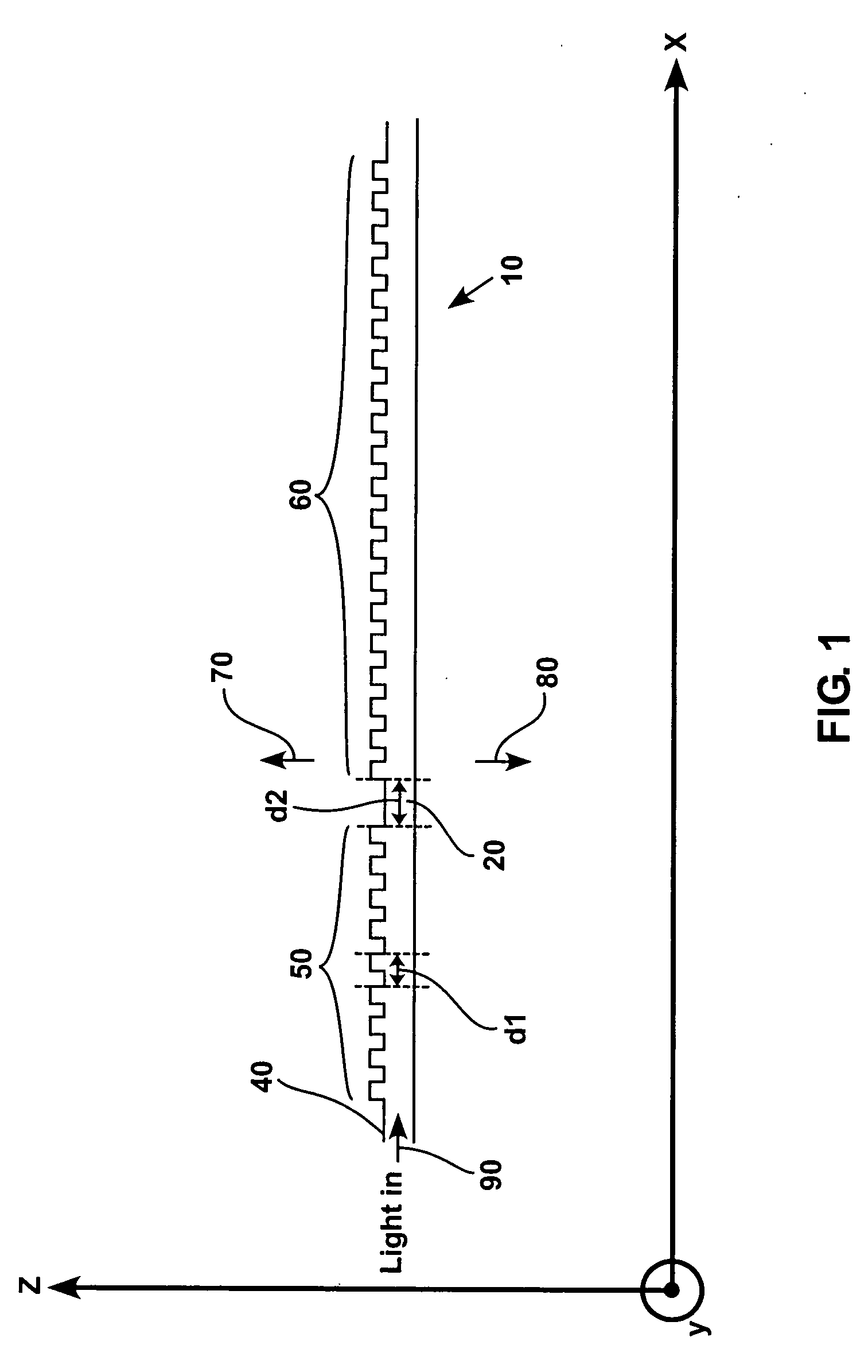
[0030]FIG. 1 discloses a cross sectional view of an exemplary embodiment of a coupler 10 with a defect 20 for an improved extraction of light around a right angle.

[0031] Referring to FIG. 1, light comes in to the coupler 10 from a waveguide 40 and is extracted up and down in the Z direction with a 90 degrees angle, as shown by arrows 70 and 80. Grates 50 are located before the defect 20 and grates 60 are located after the defect 20. The distance d1 between each grate of the grates 50 and each grate of the grates 60 corresponds to the Bragg condition for 90 degrees light extraction. In the embodiment shown in FIG. 1, the defect corresponds to a distance d2 between the last grate of the grates 50 and the first grate of the grates 60 which is different from the distance d1. The distance d2 introduced in accordance with the present disclosure depends on the profile of the extracted light and could be varied in accordance with the different uses of the coupler. For example, d2 could cor...


PUM


Abstract

An apparatus and method for increasing efficiency of grating couplers are disclosed. The apparatus through the use of a defect or a reflective element allows coupling of light around a normal or nearly normal angle with a high efficiency. The method disclosed teaches how to increase the efficiency of a grating coupler through the use of a defect or a mirror. The apparatus and method can be of particular utility in the context of optical clocking implemented with a III-V chip flip-chip bonded on a CMOS chip.

Description

CROSS-REFERENCE TO RELATED APPLICATIONS [0001] The present application claims the benefit of U.S. provisional Patent Application Ser. No. 60 / 568,729, filed May 6, 2004 for “Grating Coupler with Defect Mode” by Jeremy Witzens, the disclosure of which is incorporated herein by reference.GOVERNMENT INTEREST [0002] The research carried out in the subject application was supported in part by grants from the Air Force Office of Scientific Research (AFOSR Program “Optical Logic with Gain” under contract N. F49620-03-1-0418) and the National Science Foundation (grant no. ECS-0335110). The U.S. Government may have rights in any patent issuing on this application.BACKGROUND [0003] 1. Field [0004] The present disclosure relates to grating couplers capable of coupling light around a normal or nearly normal angle with a high efficiency. In particular, it relates to a resonantly enhanced grating coupler, for example a grating coupler with defect mode. [0005] 2. Related Art [0006] Grating couplers...

Claims


Application Information

Patent Timeline
IPC IPC(8): G02B6/124G02B6/27G02B6/34G02B6/42
CPCG02B6/124G02B6/4206G02B6/2706
Inventor WITZENS, JEREMYSCHERER, AXEL
Owner CALIFORNIA INST OF TECH
Why Eureka
Try Eureka