Insufflating optical surgical instrument

Inactive Publication Date: 2005-12-29
APPL MEDICAL RESOURCES CORP
View PDF56 Cites 184 Cited by
  • Summary
  • Abstract
  • Description
  • Claims
  • Application Information

AI Technical Summary

Benefits of technology

[0009] The invention is directed to surgical instruments providing visual entry and visual insufflation with minimal risks of injury to organs, tissues and vessels underlying a body wall. It is appreciated that the concept of the invention may be applied to any surgical instrument that provides the ability to insufflate under direct vision of the site of insufflation, regardless of the size

Problems solved by technology

It is well known that establishing access to a non-inflated peritoneal cavity can be a very dangerous part of any laparoscopic procedure.
Unfortunately, insertion of the needle has been required without any visual aid to facilitate location of the sharp needlepoint.
This is a highly mechanical event at best and offers less than optimal arrangement.
As pointed out above, a drawback of this procedure is it is performed blindly.
A consequence of this blind insertion is the surgeon may inadvertently damage the organs and tissues underlying the abdominal wall such as major blood vessels and the intestinal tract.
Once access is gained, it can take several minutes for the gas to insufflate the abdomen and while this is happening the surgeo

Method used


Image

  • Insufflating optical surgical instrument
  • Insufflating optical surgical instrument
  • Insufflating optical surgical instrument

Examples


Example

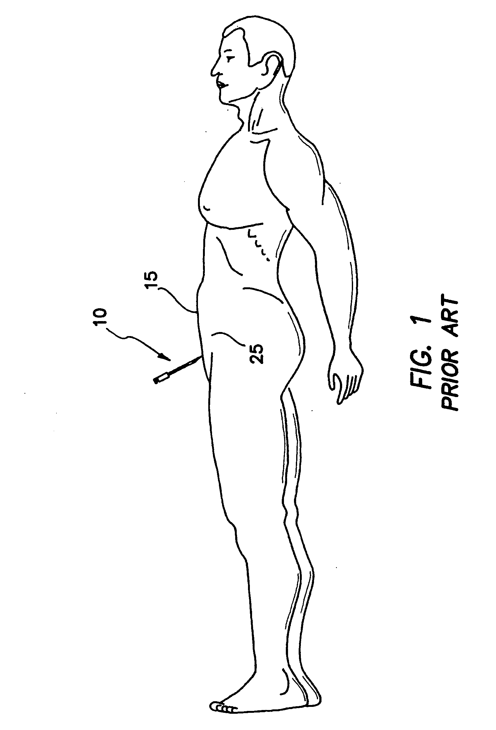
[0038] Referring to FIG. 1, there is shown a typical laparoscopic abdominal surgery where an inflation needle 10 is inserted through a body or abdominal wall 15 and into an abdominal cavity 25. A gas is passed through the needle 10 to create a space within the abdominal cavity 25. This procedure is referred to as insufflation. The needle 10 is referred to as an insufflation needle and the gas supply is referred to as an insufflation gas. The insufflation needle 10 is placed through the body wall 15 blindly. In other words, there is no direct visualization of the procedure from the inside of the body wall 15. As explained earlier, the current procedure may inadvertently damage organs and tissues underlying the body or abdominal wall 15 such as major blood vessels and the intestinal tract. It is not uncommon for there to be internal structures attached to the internal side of the body wall 15. This is especially so in the case of the abdominal cavity 25. Portions of the intestines, co...


PUM


Abstract

An insufflating surgical instrument adapted for movement across an abdominal wall to insufflate an abdominal region of a patient is disclosed comprising a shaft having an insufflation channel extending along an axis between a proximal end and a distal end, the insufflation channel being adapted for connection to a source of fluid under pressure at the proximal end, a tip at the distal end of the shaft, and at least one vent hole formed at the tip or the shaft being in connection with the insufflation channel and being adapted to expel the fluid under pressure to insufflate the abdominal region. At least one of the tip and the shaft is formed of a translucent or transparent material such as polycarbonate to facilitate visualization of the abdominal wall and the abdominal region. The shaft includes a lumen extending along the axis between the proximal end and the distal end to enable insertion of a laparoscope. The lumen and insufflation channel may be formed as separate channels or as one shared channel. The tip may be blunt, the shaft and the tip may be integrally formed, and the vent hole may be of any geometric shape including round, oval, square and rectangular. The blunt tip may further comprise a marker to indicate penetration of the abdominal wall. In another aspect, the tip may be sharp, pointed or bladed to facilitate penetration of body tissue.

Description

[0001] This is a non-provisional application claiming the priority of provisional application Ser. No. 60 / 584,302, filed on Jun. 29, 2004, entitled “Insufflating Optical Surgical Instrument,” which is fully incorporated herein by reference. This non-provisional application is also filed as a continuation-in-part application claiming the priority of patent application Ser. No. 10 / 956,167, filed on Oct. 1, 2004, entitled “Bladeless Optical Obturator,” which is fully incorporated herein by reference.BACKGROUND OF THE INVENTION [0002] 1. Field of the Invention [0003] This invention generally relates to surgical instruments and, in particular, to surgical instruments providing visual entry and visual insufflation. [0004] 2. Discussion of the Prior Art [0005] Laparoscopic surgery of the abdominal area typically requires the introduction of an insufflation gas into the peritoneal cavity of the patient. The insufflation gas is usually pressurized to about 10 mm Hg above atmospheric pressure...

Claims


Application Information

Patent Timeline
IPC IPC(8): A61B17/34A61B19/00
CPCA61B17/3417A61B17/3462A61B17/3474A61B2017/349A61B19/5212A61B2017/3454A61B2017/346A61B17/3494A61B90/361A61M13/003A61B1/06A61M2202/0007A61M2202/02A61M2202/0468A61M2205/3337
Inventor ALBRECHT, JEREMY J.BRUSTAD, JOHN R.TAYLOR, SCOTT V.JOHNSON, GARY M.HILAL, NABIL
Owner APPL MEDICAL RESOURCES CORP
Why Eureka
Try Eureka