Digital filter design method and device, digital filter design program, digital filter

a filter circuit and design method technology, applied in the field of digital filter design methods and devices, digital filter design programs, digital filters, can solve the problems of difficult to set window functions or approximate expressions appropriately, difficult to obtain preferable target frequency characteristics, and large number of taps and multipliers of filter circuits, so as to reduce the number of taps and multipliers, the structure of the digital filter is extremely simple, and the effect of reducing the number of multipliers

Inactive Publication Date: 2005-12-29
NSC CO LTD
View PDF3 Cites 6 Cited by
  • Summary
  • Abstract
  • Description
  • Claims
  • Application Information

AI Technical Summary

Benefits of technology

[0014] The present invention having such a structure can significantly reduce the number of taps and the number of multipliers used as compared to the conventional FIR filter and make the structure of the digital filter extremely simple. Furthermore, windowing for reducing the number of filter coefficients no longer needs to be performed and the filter impulse response also becomes a finite-base function, and therefore it is possible to obtain a preferable frequency characteristic having no discretization error and having a great attenuation amount out of band. Therefore, it is possible to realize an FIR digital filter having a desired frequency characteristic on a small circuit scale and with high accuracy. Furthermore, the present invention allows a desired digital filter to be constructed by only combining basic filters and allows even non-skilled technicians to design an FIR digital filter having a desired frequency characteristic extremely simply.

Problems solved by technology

The number of coefficients obtained in this way becomes enormous and using all those coefficients will result in an extremely large number of taps and multipliers of the filter circuit, which is unrealistic.
However, the frequency characteristic of the FIR filter obtained using the conventional design method depends on a window function and approximate expression, and therefore unless these are correctly set, it is not possible to obtain a preferable target frequency characteristic.
However, it is generally difficult to set the window function or approximate expression appropriately.
Furthermore, performing windowing to reduce the number of filter coefficients causes a discretization error in the frequency characteristic.
For this reason, there has been a problem that it is very difficult to realize a desired frequency characteristic using the conventional filter design method.
Furthermore, obtaining a desired frequency characteristic using the conventional filter design method requires a trial and error method of subjecting the filter coefficients obtained to an FFT while checking the frequency characteristic.
Thus, the conventional art requires skilled technicians to take time and trouble its design for and has a problem that it is not easy to design an FIR filter of a desired characteristic easily.
Furthermore, in designing an FIR filter capable of realizing a desired frequency characteristic as accurately as possible, there is a limit to the number of filter coefficients that can be reduced by windowing.
For this reason, the number of taps of the designed FIR filter becomes enormous and its filter coefficient values become very complicated and random values.
Thus, there is also a problem that realizing such a number of taps and filter coefficient values requires a large-scale circuit structure (adders, multipliers).
However, even using one of these methods can only narrow the pass band of the filter and cannot realize a frequency characteristic of an arbitrary shape with a small number of taps.

Method used


Image

  • Digital filter design method and device, digital filter design program, digital filter
  • Digital filter design method and device, digital filter design program, digital filter
  • Digital filter design method and device, digital filter design program, digital filter

Examples


Embodiment Construction

[0055] With reference now to the attached drawings, an embodiment of the present invention will be explained below. Noting an aspect that a convolution of impulse responses corresponds to summation of frequency responses in the impulse response on the time axis and a frequency characteristic on the frequency axis correlating with each other, this embodiment provides a completely new filter design method which is fundamentally different from a conventional design method which takes a calculation of filter coefficients as a starting point, and a digital filter which is a product thereof.

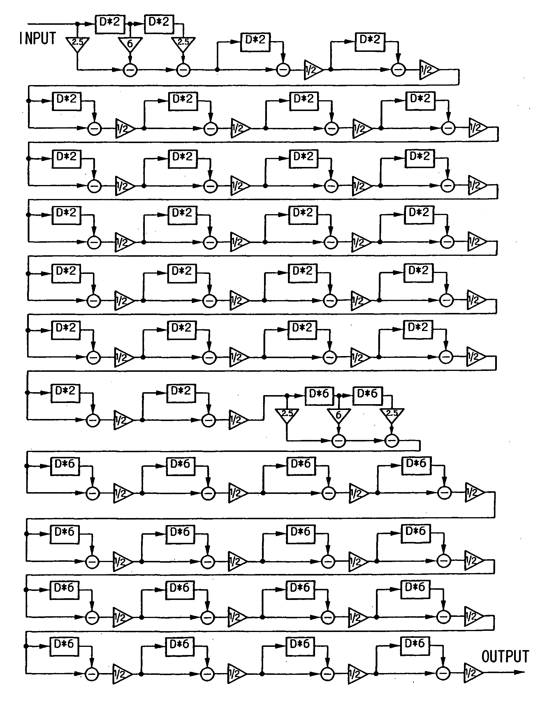
[0056] That is, this embodiment defines several types of basic filters having specific impulse responses and realizes an FIR filter having a desired frequency characteristic in the form of cascade connecting the basic filters in an arbitrary way. The basic filters can be roughly divided into three types; basic low pass filter, basic high pass filter and basic band pass filter (including a comb-shaped ...


PUM


Abstract

A numerical string consisting of a ratio of “−1, m, −1” or “1, m, 1” is subjected to a predetermined moving average calculation n times. A numerical string thus obtained is used as filter coefficients of a basic filter and at least one basic filter is combined in an arbitrary way for cascade connection, thereby calculating the filter coefficients of the digital filter to be obtained. This significantly reduces the number of taps and the number of multipliers used as compared to the conventional FIR filter. Moreover, by using the numerical strings “−1, m, −1” and “1, m, 1” so that the filter impulse response becomes a finite-base function, it is possible to obtain a preferable frequency characteristic having no discretization error and having a great attenuation amount out of band.

Description

BACKGROUND OF THE INVENTION [0001] 1. Field of the Invention [0002] The present invention relates to a digital filter design method and device, digital filter design program, digital filter, and more particularly, to a type of FIR filter which is provided with tapped delay lines made up of a plurality of delayers, multiplies output signals of the respective taps several-fold, adds up the multiplication results and outputs the addition result, and a design method therefor. [0003] 2. Description of the Related Art [0004] An FIR (Finite Impulse Response) filter is one type of digital filter. This FIR filter is a type of filter which is provided with tapped delay lines made up of a plurality of delayers, multiplies output signals of the respective taps several-fold, adds up the multiplication results and outputs the addition result, and has the following advantages. First, since the poles of a transfer function of the FIR filter exists only at the origin of the z-plane, the circuit is a...

Claims


Application Information

Patent Timeline
Patent Type & Authority Applications(United States)
IPC IPC(8): G06F17/10H03H17/06
CPCH03H2017/0072H03H17/06
Inventor KOYANAGI, YUKIO
Owner NSC CO LTD
Why Eureka
Try Eureka