

Cre-lox based method for conditional RNA interference
- Summary
- Abstract
- Description
- Claims
- Application Information
AI Technical Summary
Benefits of technology
Problems solved by technology
Method used
Image

Examples
example 1
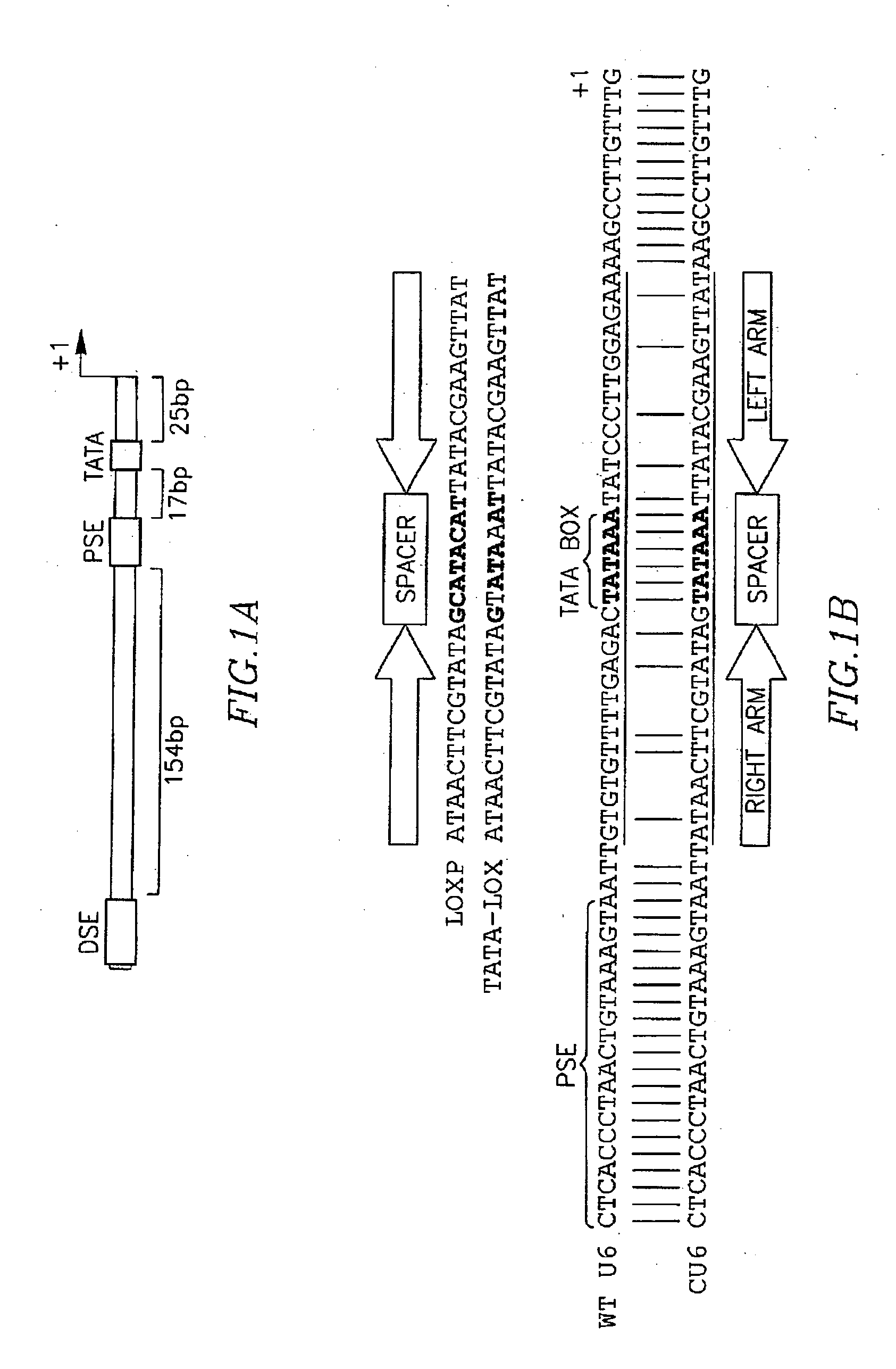
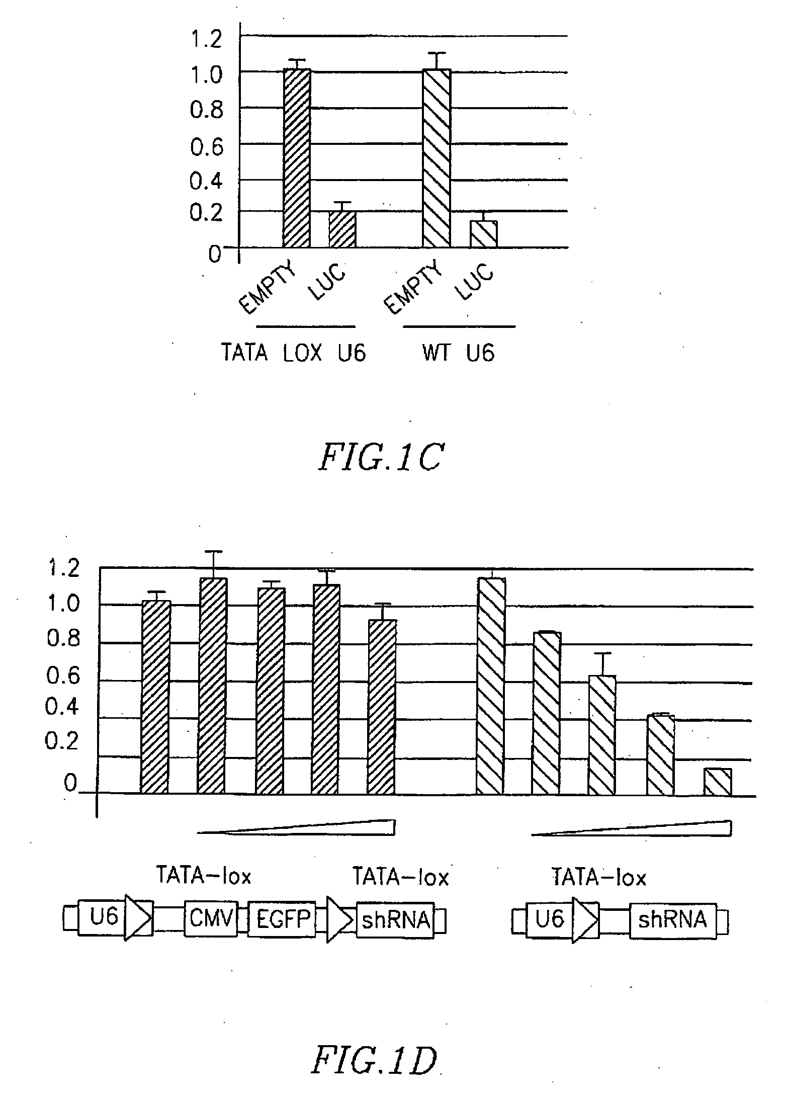
Functional TATA-Lox-Modified U6 Promoter
Materials and Methods
Generation of Plasmids
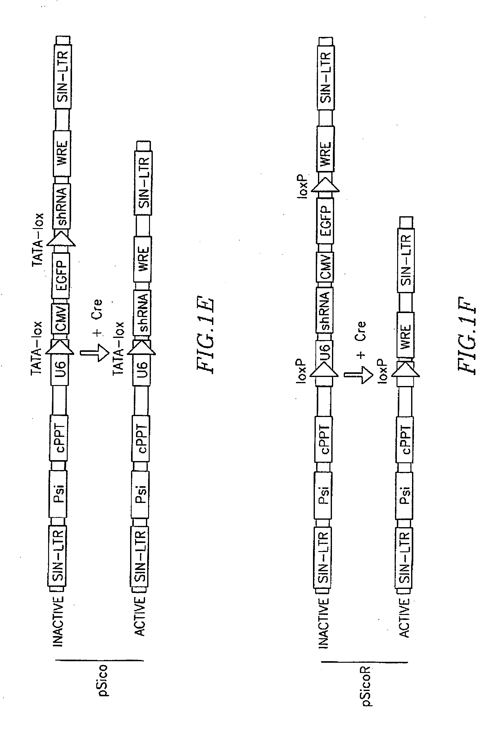
[0176] To generate pSico the lox-CMV-GFP-lox cassette was removed from lentilox 3.7 (pLL3.7) (Rubinson, D. A., et al. (2003) Nat Genet 33, 401-6) by digesting with BfuAI and PciI, followed by filling-in and religation. The first TATAlox followed by the terminator and by an EcoRI was inserted in the resulting plasmid by PCR-mediated mutagenesis using the following oligos:
(SEQ ID NO: 1)pSico6Eco: GAATTCAACGCGCGGTGACCCTCGAGG(SEQ ID NO: 2)pSico6: ASAAAAAACCAAGGCTTATAACTTCGTATAATTTATACTATACGAAGTTATAATTACTTTACAGTTACCC
[0177] To insert the second TATAlox preceded by a NotI site the resulting plasmid was digested with EcoRI and XhoI and ligated to the following annealed oligos:
(SEQ ID NO: 3)TATALOX F:AATTCGAOAGGCGGCCGCATAACTTCGTATAGTATAAATTATACGAAGTTATAAGCCTTGTTAACGCGCGGTGACCC(SEQ ID NO: 4)TATALOX R:TCGAGGGTCACCGCGCGTTAACAAGGCTTATAACTTCGTATAATTTATACTATACGAAGTTATGCGGCCGCCTCTCG
[0178] The resulting constr...
example 2
Conditional shRNA Expression with TATA-Lox U6 Promoters
Materials and Methods
Plasmids:
[0186] The CMV-GFP cassette was amplified from pLL3.7 (Rubinson, D. A., et al, (2003) Nat Genet 33, 401-6.)
[0187] The complete sequence of the cU6-CMV-EGFP-TATAlox-shRNA:
(SEQ ID NO: 11)GATCCGACGCCGCCATCTCTAGGCCCGCGCCGGCCCCCTCGCACAGACTTGTGGGAGAAGCTCGGCTACTCCCCTGCCCCGGTTAATTTGCATATAATATTTCCTAGTAACTATAGAGGCTTAATGTGCGATAAAAGACAGATAATCTGTTCTTTTTAAIACTAGCTACATTTTACATGATAGGCTTGGATTTCTATAAGAGATACAAATACTAAATTATTATTTTAAAAAACAGCACAAAAGGAAACTCACCCTAACTGTAAAGTAATTATAACTTCGTATAGTATAAATTATACGAAGTTATAAGCCTTGGTTTTTTGAATTCCGTATTACCGCCATGCATTAGTTATTAATAGTAATCAATTACGGGGTCATTAGTTCATAGCCCATATATGGAGTTCCGCGTTACATAACTTACGGTAAATGGCCCGCCTGGCTGACCGCCCAACGACCCCCGCCCATTGACGTCAATAATGACGTATGTTCCCATAGTAACGCCAATAGGGACTTTCCATTGACGTCAATGGGTGGAGTATTTACGGTAAACTGCCCACTTGGCAGTACATCAAGTTGTATCATATGCCAAGTACGCCCCCTATTGACGTCAATGACGGTAAATGGCCCGCCTGGCATTATGCCCAGTACATGACCTTATGGGACTTTCCTACTTGGCAGTACATCTACGTATTAGTCATCGCTATTACCATGGTGATGCGGTTT...
example 3
Conditional Endogenous Gene Silencing with Lentiviral Vectors Containing TATA-Lox U6 Promoters Driving shRNA Expression
Materials and Methods
Generation of a Self-Inactivating Lentiviral Vector Containing a Conditional TATA-lox U6:
[0192] To generate pSico the lox-CMV-GFP-lox cassette was removed from lentilox 3.7 (pLL3.7) (Rubinson, supra) by digesting with BfuAI and PciI followed by filling-in and religation. The first TATAlox followed by the terminator and by an EcoRI was inserted in the resulting plasmid by PCR-mediated mutagenesis using the following oligos:
(SEQ ID NO: 1)pSico6Eco GAATTCAACGCGCGGTGAGCCTCGAGG(SEQ ID NO: 13)pSico6 AS AAAAAACCAAGGCTTATAACTTCGTATAATTTATACTATACGAAGTTATAATTACTTTACAGTTACCC.
[0193] To insert the second TATAlox preceded by a NotI site the resulting plasmid was digested with EcoRI and XhoI and ligated to the annealed oligos, TATALOX F (SEQ ID NO: 3) (Example 1), and TATALOXR (SEQ ID NO: 4) (Example 1).
[0194] The resulting construct was finally digeste...
PUM
| Property | Measurement | Unit |
|---|---|---|
| Gene expression profile | aaaaa | aaaaa |
Abstract
Description
Claims
Application Information