Weather strip and mounting structure thereof

a technology of weather strip and mounting structure, which is applied in the field of weather strip, can solve the problems of narrow gap between the hollow seal part and the hollow seal part, and it is difficult to insert the fold back portion of the retainer into the fold back portion, so as to improve the assembly performance

Inactive Publication Date: 2006-01-05
TOYODA GOSEI CO LTD
View PDF14 Cites 9 Cited by
  • Summary
  • Abstract
  • Description
  • Claims
  • Application Information

AI Technical Summary

Benefits of technology

[0006] The invention was made with a view to solving the problems and objects thereof is to provide a weather strip in which assemble performance is improved, and a mounting structure of such the weather strip.

Problems solved by technology

In the event that a relatively large hollow seal part is extruded, however, there exists a risk that the hollow seal part sags after extrusion, whereby the hollow seal part and the mount base part are caused to attach to each other.
In addition, even in the event that the two parts are successfully kept apart from each other, due to the hollow seal part sagging, the hollow seal part overhangs the mount base part, narrowing a gap between the two parts.
Due to this, it becomes difficult to insert a fold back portion of the retainer into the gap between the hollow seal part and the mount base part, for engaging the fold back portion with an end portion of the mount base part.
Namely, there has existed a risk that it becomes difficult to fit the mount base part in the retainer.
Since the fitting of the mount base part must generally be performed by an assembling operator who relies not on sight but on touching, the aforesaid problem appears significantly.

Method used


Image

  • Weather strip and mounting structure thereof
  • Weather strip and mounting structure thereof
  • Weather strip and mounting structure thereof

Examples


Embodiment Construction

[0028] Hereinafter, one embodiment of the invention will be described by reference to the drawings.

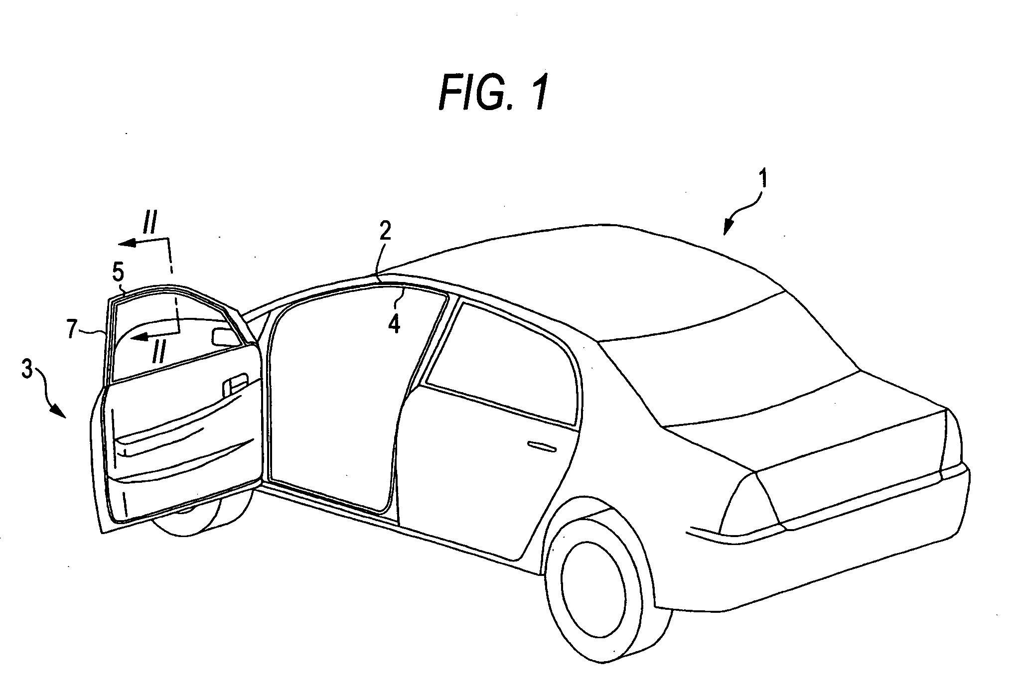
[0029] As shown in FIG. 1, an automobile door (in the figure, a front door; hereinafter, referred simply to as a door) 3 is provided in an opening 2 in an automobile body 1 as a vehicle (a vehicle main body) in such a manner as to be opened and closed. In addition, a weather strip 4 is securely mounted around the opening 2 in the automobile body 1 for establishing a seal between the automobile body 1 and the door 3. Similarly, a door weather strip 5 is securely mounted on the door 3 in such a manner as to conform to an outer peripheral shape of the door 3.

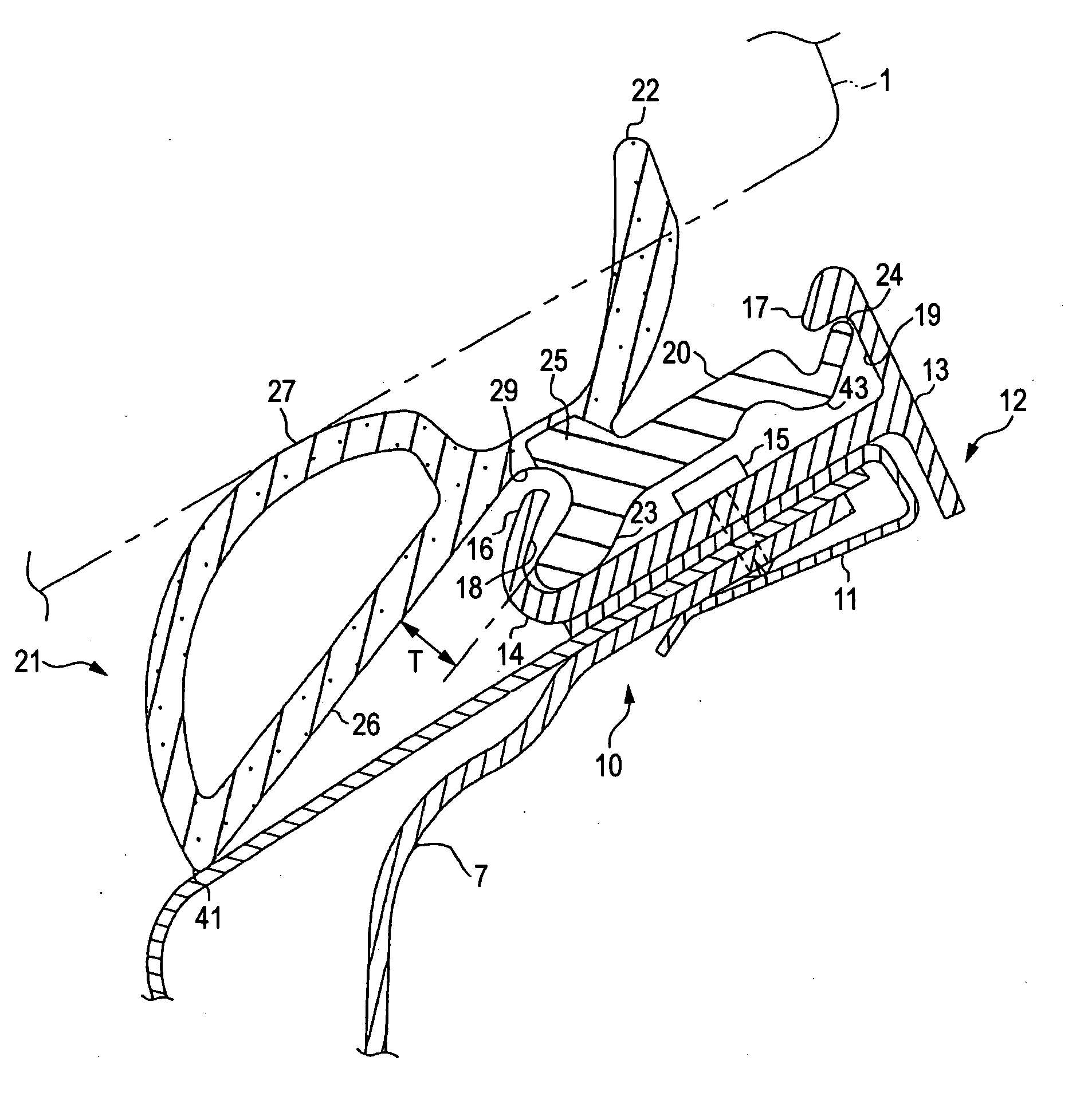
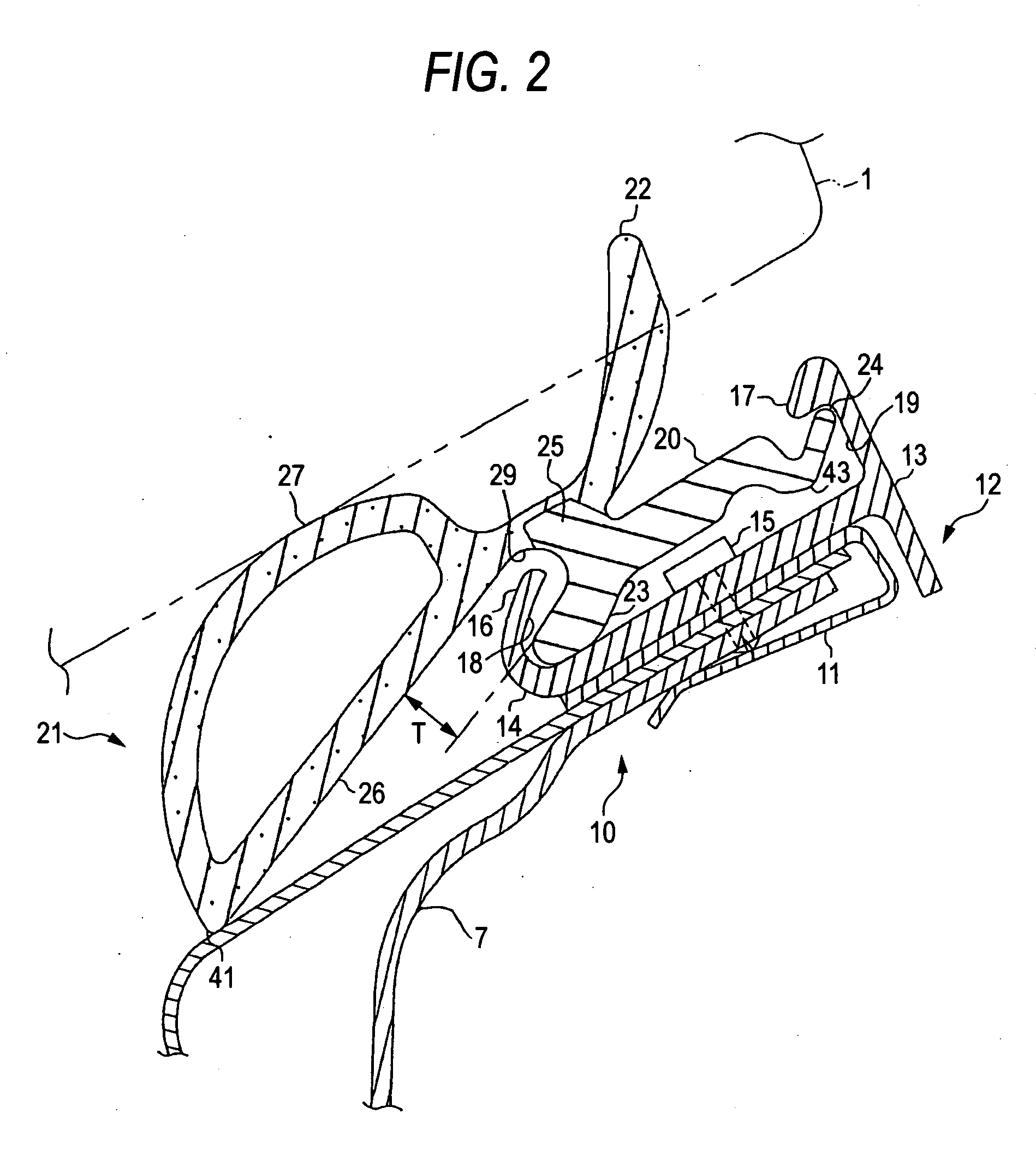
[0030] Next, referring to FIG. 2 which is a cross-sectional view of a portion of the door taken along the line II-II in FIG. 1, the configuration of the door weather strip 5 and a mounting structure thereof will be described in detail based on the configuration of a portion of a door frame 7.

[0031] The door frame 7 includes a flat ...


PUM

PropertyMeasurementUnit
elasticaaaaaaaaaa
pressureaaaaaaaaaa
rigidityaaaaaaaaaa

Abstract

A weather strip adapted to be mounted on a door of a vehicle: the weather strip has a mount base part including an interior-side engagement portion and an exterior-side engagement portion which are engageable with a pair of engagement recesses provided on a mount portion of a door. A neck portion extends from the interior-side engagement portion. A hollow seal part includes a bottom wall portion extending from the neck portion substantially linearly and substantially in parallel with the interior-side engagement portion of the mount base part. A predetermined space is formed between the bottom wall portion and the interior-side engagement portion. A seal wall is provided on a side of the bottom wall portion which is opposite to a surface of the bottom wall portion facing the interior-side engagement portion.

Description

BACKGROUND OF THE INVENTION [0001] 1. Field of the Invention [0002] The present invention relates to a weather strip that is mounted on a door of a vehicle. [0003] 2. Related Art [0004] Conventionally, a door weather strip is mounted on a peripheral portion of a door of a vehicle such as an automobile. The door weather strip includes a mount base part that is mounted on a retainer having a substantially C-shaped cross section that is provided along the peripheral portion of the door, and a hollow seal part and a seal lip which are formed integrally with the mount base part, and most of the weather strip is formed through a so-called extrusion. When the door is closed, the hollow seal part and the seal lip of the door weather strip are brought into pressure contact with a peripheral portion around a door opening in a body of the automobile (for example, refer to JP-H07-21413U). [0005] In the event that a relatively large hollow seal part is extruded, however, there exists a risk that...

Claims


Application Information

Patent Timeline
Patent Type & Authority Applications(United States)
IPC IPC(8): E06B7/16B29K21/00
CPCB60J10/0005B60J10/085B60J10/0062B60J10/0031B60J10/16B60J10/24B60J10/30B60J10/86
Inventor MUGISHIMA, SATOSHIGOTO, TERUHITO
Owner TOYODA GOSEI CO LTD
Why Eureka
Try Eureka