Fluid filter

a filter and flue gas technology, applied in the field of flue gas filters, can solve the problems of paint droplets passing through the filter in a very large range of sizes, paper filters in paint arrestance, and paper filters that are not effective barrier filters, etc., and achieve the effect of retaining more particulates and high particulate exposur

Inactive Publication Date: 2006-01-05
PROD UNLIMITED
View PDF11 Cites 60 Cited by
  • Summary
  • Abstract
  • Description
  • Claims
  • Application Information

AI Technical Summary

Benefits of technology

[0033] Still another object of the invention is to provide a fluid filter of the type described above wherein the zones having a higher particulate exposure due to the high...

Problems solved by technology

For example, expanded paper filters are typically not effective barrier filters because of the large individual openings through the expanded paper filter.
The main drawback with paper filters in paint arrestance applications lies in the fact that paint droplets passing through the filters exist in a very large range of sizes.
Even so, the restriction of the opening size increases the pressure drop through the media, thereby increasing the energy required to move air through the filter media and ultimately requiring replacement of the filter.
This loading obviously restricts the opening size and thereby increases the pressure drop of the filter media.
First, there is an increased cost in view of the metal material utilized and the lamination/pleating steps.
Second, safety risks increase during the handling of the metal mesh due to the very sharp edges of the mesh.
An increase in disposal and recycling problems are created by the combination of metal and otherwise disposable fibrous products.
Finally, there is a lack of tensile strength in this type of filter media.
In order to utilize the pleated material described above, it must be adequately supported by an external frame, adding to the increased cost referenced above.
Otherwise, any application of tensile forces perpendicular to the pleat lines of the filter media ...

Method used


Image

  • Fluid filter
  • Fluid filter
  • Fluid filter

Examples


Embodiment Construction

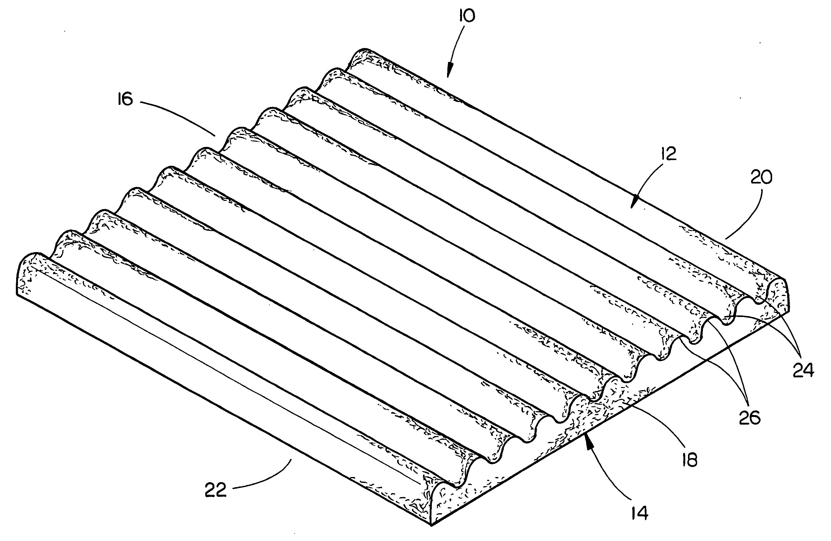
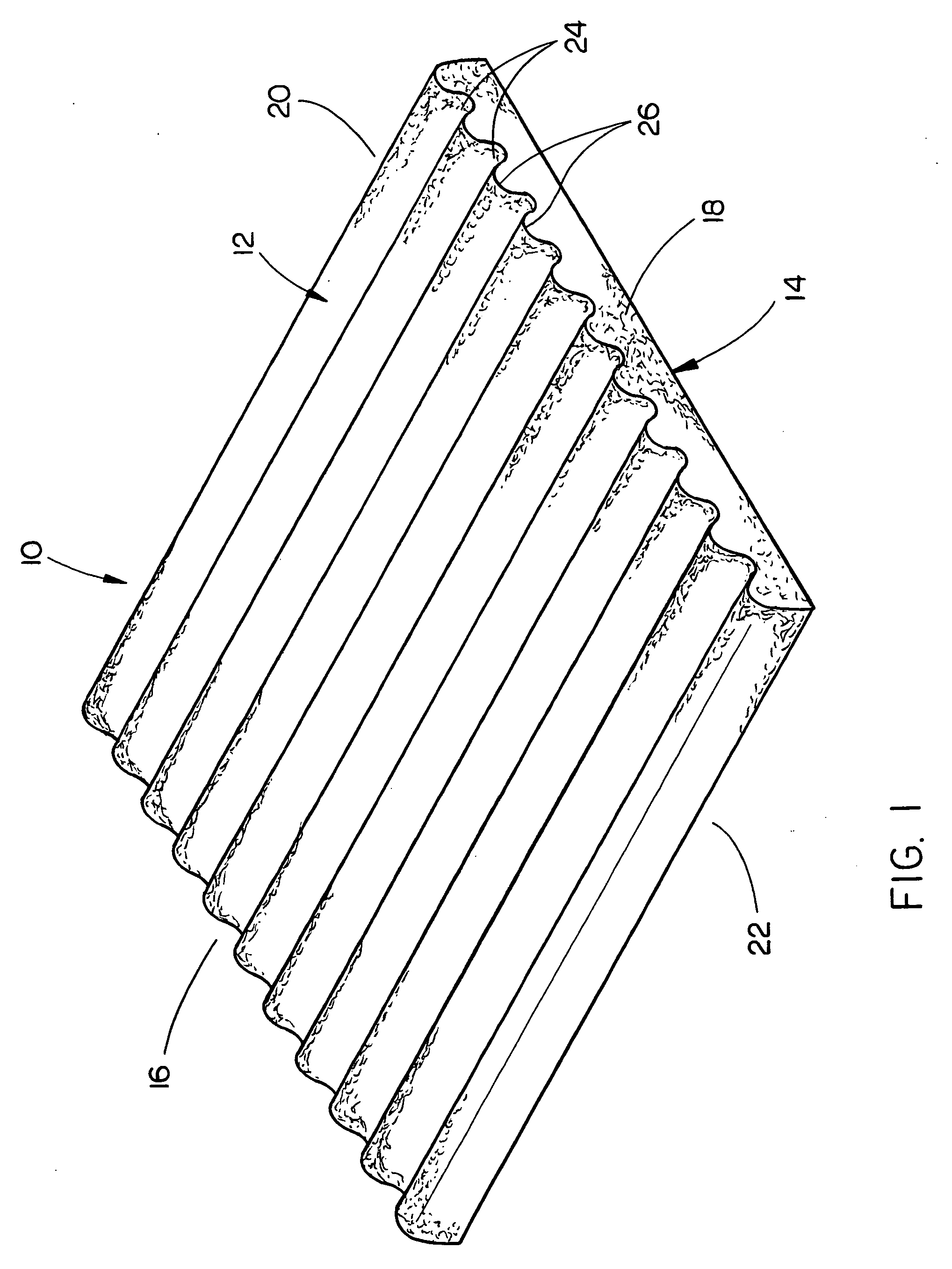
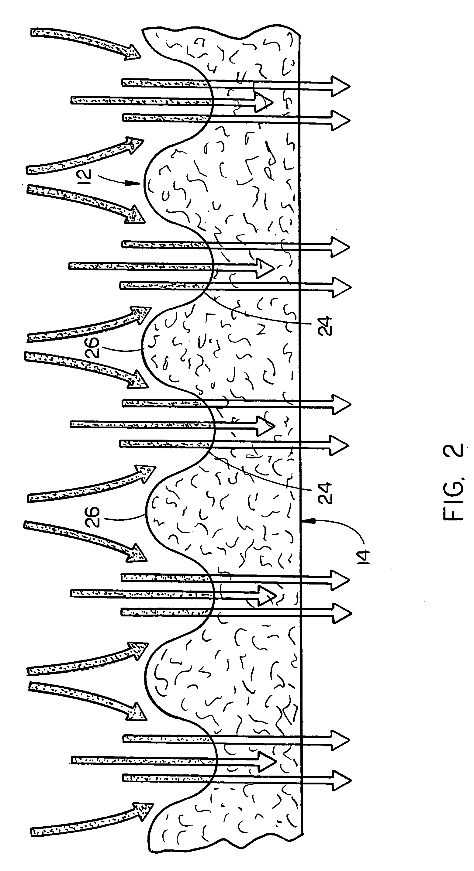
[0040] Referring now to the drawings, in which similar or corresponding parts are identified with the same reference numeral, and more particularly to FIG. 1, the fluid filter or filtration media of the present invention is generally designated by the reference numeral 10 which is comprised of a layer of fluid-permeable material having an upper surface 12, lower surface 14, opposite side edges 16 and 18, and opposite ends 20 and 22. As seen in FIGS. 1-3, the filtration media 10 of this invention has a thickness measured between the upper and lower surfaces 12 and 14 which is non-constant. The non-constant thickness is achieved by providing a series of spaced-apart grooves 24 extending into the upper surface 12. The spaced-apart grooves 24 each have a generally U-shaped cross section. The series of alternating grooves 24 are separated by a plurality of alternating ridges 26 which each have a generally inverted U-shaped cross section.

[0041] The variable thickness filtration media of ...


PUM

PropertyMeasurementUnit
Lengthaaaaaaaaaa
Thicknessaaaaaaaaaa
Electrical resistanceaaaaaaaaaa

Abstract

A fluid filter is disclosed which comprises a layer of high loft, non-woven, fibrous, fluid-permeable material having a length and a width, an upper surface, a lower surface, and a thickness measured between the upper and lower surfaces which is non-constant. The non-constant thickness is achieved by providing a series of spaced-apart grooves separated by a series of spaced-apart ridges. The lower surface is substantially planar and the grooves each have a generally U-shaped cross section with the ridges having a generally inverted U-shaped cross section. A modified form of the invention is also disclosed wherein the zones of higher flow resistance have a greater density than the zones of lower flow resistance. In this embodiment, the thickness of the filter is constant. The method of filtering particulate material from a fluid stream is also disclosed.

Description

BACKGROUND OF THE INVENTION [0001] 1. Field of the Invention [0002] This invention relates generally to a fluid filter and more particularly to a fluid filter having different pressure drop / flow rate zones across the width and / or length thereof. More particularly, this invention relates to a filter for the removal of particulate from a fluid comprised of a batting of high loft, non-woven, fibrous, fluid-permeable material having alternating zones of higher and lower fluid flow resistance wherein every two zones of higher flow resistance are separated by a zone of lower flow resistance and every two zones of lower flow resistance are separated by a zone of higher flow resistance. [0003] 2. Description of the Related Art [0004] Many materials and combinations of materials, have been used as filtration media or fluid filters to remove solid or liquid particulate from fluid streams. The capabilities of such fluid filters are judged according to three main criteria: (1) the particulate r...

Claims


Application Information

Patent Timeline
IPC IPC(8): B01D46/00B01D39/16
CPCB01D39/1615B01D2201/184B01D39/1623A63F13/49
Inventor BEIER, SCOTT B.POSPISAL, GARY L.
Owner PROD UNLIMITED
Why Eureka
Try Eureka