Insulated container with thermoelectric unit

a technology of thermoelectric units and containers, applied in the direction of container discharging methods, domestic cooling apparatus, lighting and heating apparatus, etc., can solve the problems of increasing the associated freight cost and reducing the efficiency of thermoelectric insulated coolers, so as to reduce heat loss, reduce freight costs, and minimize the overall size of thermoelectric units

Active Publication Date: 2006-01-05
THE COLEMAN CO INC
View PDF16 Cites 47 Cited by
  • Summary
  • Abstract
  • Description
  • Claims
  • Application Information

AI Technical Summary

Benefits of technology

[0015] Linearly aligning the components of the thermoelectric unit minimizes the overall size of the thermoelectric unit and thus reduces freight costs. It also permits a single, smaller opening in the insulated cooler to be provided for installation of the thermoelectric unit. The smaller opening reduces heat loss, increasing efficiency of the thermoelectric insulated container. The components of the thermoelectric unit may be arranged in a manner other than linearly, but providing the components in another arrangement may increase the associated freight costs and decrease the efficiency of the thermoelectric insulated cooler.
[0016] In accordance with an embodiment, a thermally conductive block is mounted on the cold side of the thermoelectric module to provide a spacer to permit the cold side heat sink to be mounted on the interior of the insulated container and the hot side heat sink to be mounted on the exterior of the insulated container, as well as to transfer heat from the inside of the cooler to the outside of the cooler. In accordance with an embodiment, insulation is blown around this thermally conductive block to minimize heat loss through the thermoelectric unit.
[0017] The thermoelectric unit of the present invention may also include one or more of the following: electrical wires and connectors for the hot and cold side fan and motor unit units and the thermoelectric module, thermal switches, holders for the thermoelectric module and thermal switches, fasteners for joining components, foam insulations, and fan covers for the hot or cold side fans. The entire thermoelectric unit may be assembled in one location and may be connected to the insulated container in another location, providing an opportunity for the thermoelectric unit to be assembled in a lower-cost labor market (e.g., overseas) and to be shipped to a local facility for assembly with the insulated container. This feature significantly reduces the need for local labor while maximizing the efficiency of the thermoelectric coolers.

Problems solved by technology

The components of the thermoelectric unit may be arranged in a manner other than linearly, but providing the components in another arrangement may increase the associated freight costs and decrease the efficiency of the thermoelectric insulated cooler.

Method used


Image

  • Insulated container with thermoelectric unit
  • Insulated container with thermoelectric unit
  • Insulated container with thermoelectric unit

Examples


Embodiment Construction

[0023] In the following description, various embodiments of the present invention will be described. For purposes of explanation, specific configurations and details are set forth in order to provide a thorough understanding of the embodiments. However, it will also be apparent to one skilled in the art that the present invention may be practiced without the specific details. Furthermore, well-known features may be omitted or simplified in order not to, obscure the embodiment being described.

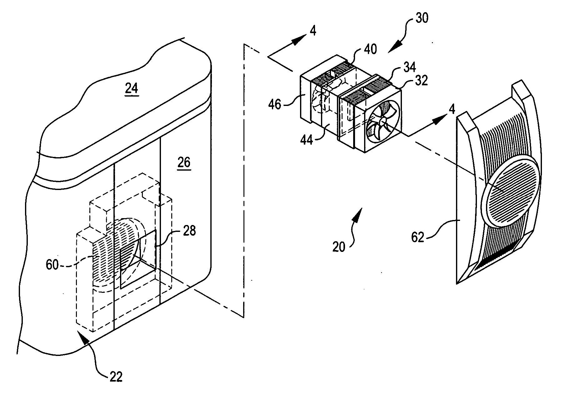
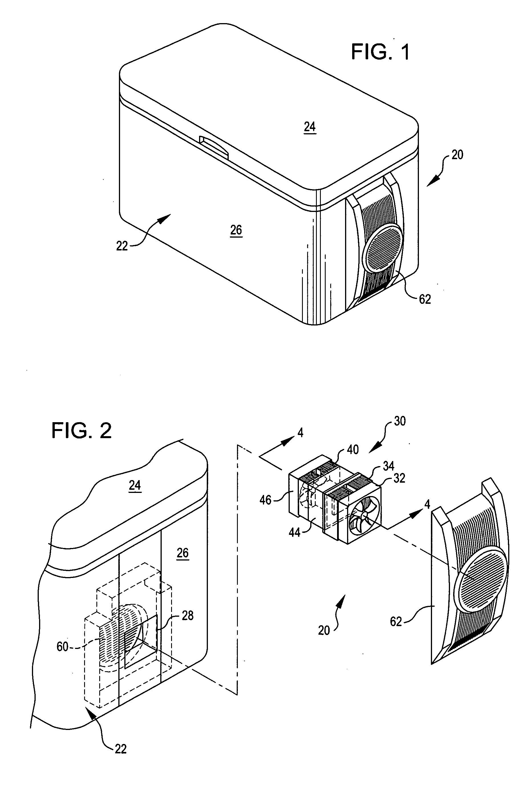
[0024] Referring now to the drawings, in which like reference numerals represent like parts throughout the several views, FIG. 1 shows a thermoelectric insulated container 20 incorporating an embodiment of the present invention. The thermoelectric insulated container 20 includes an insulated container 22 having a top 24, sides 26, and a bottom (not shown in the drawing). The insulated container 22 shown in the drawings is shaped like a conventional chest cooler, but other configurations may be ...


PUM


Abstract

A thermoelectric unit for a thermoelectric insulated container. The thermoelectric unit is configured to be inserted in a small opening in the insulated container. A cold side heat sink is mounted on the portion of the thermoelectric unit that extends inside of the insulated container, and a hot side heat sink is mounted on a portion of the thermoelectric unit that extends outside. The thermoelectric unit is arranged so that a thermoelectric module for the thermoelectric unit, the cold side heat sink, and the hot side heat sink are aligned linearly. A hot side fan and motor unit is mounted on the outside of the hot side heat sink and a cold side fan and motor unit is mounted on the outside of the cold side heat sink. The hot and cold side fan and motor units may also be mounted linearly with the hot and cold side heat sinks.

Description

REFERENCE TO RELATED APPLICATION [0001] This application claims the benefit of U.S. Provisional Application No. 60 / 584,580, filed Jul. 1, 2004, and incorporated herein by reference.TECHNICAL FIELD OF THE INVENTION [0002] The present invention generally relates to insulated containers, and more specifically relates to insulated containers having solid state heat pumps such as thermoelectric modules. BACKGROUND OF THE INVENTION [0003] Insulated containers, also called “coolers,” are prevalent in contemporary life. The insulated containers are often used for picnics or for outdoor activities such as camping or sporting events. In addition, insulated containers are becoming more prevalent in the medical industry, where they are used to move transplant organs and other articles that need to remain cold during transport. Also, the need to transport commercial goods such as perishable food, drink, medicine, and environmental samples is becoming more important. [0004] One downside to curren...

Claims


Application Information

Patent Timeline
Patent Type & Authority Applications(United States)
IPC IPC(8): F25B21/02F17C13/00F25B21/00
CPCF25B21/02F25D2400/12F25B2321/0251F25B2321/023
Inventor CULP, YIYUNKITCHENS, MARK CHARLESCHIU, JOHNWANDRES, REGIS MARIE-JEAN
Owner THE COLEMAN CO INC
Why Eureka
Try Eureka