
System for testing performance of medical gas or vapor analysis apparatus

a technology of gas analyzer and vapor analysis apparatus, which is applied in the calibration of gas analyzers, instruments, liquid/fluent solid measurements, etc., can solve the problems of unreliable gas analyzers, waste of calibration gases, and inability to provide reliable gas analyzers, etc., and achieve the effect of facilitating the accurate calculation of partial pressur

Inactive Publication Date: 2006-01-05
AXON MEDICAL INC
View PDF0 Cites 15 Cited by
  • Summary
  • Abstract
  • Description
  • Claims
  • Application Information

AI Technical Summary

Benefits of technology

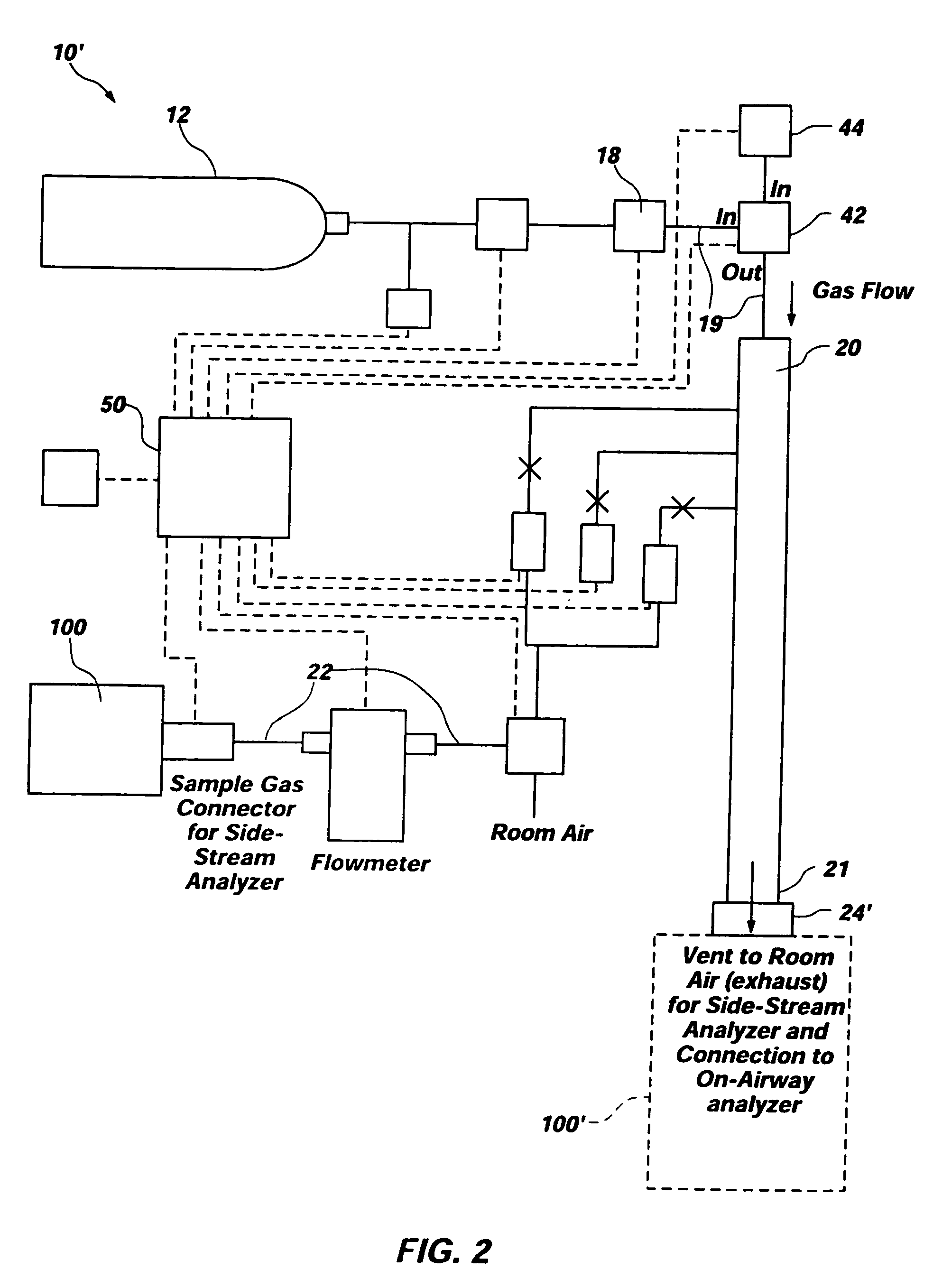
[0016] In addition, the test system may include one or more processing elements (e.g., processors, computers, etc.) that are configured to communicate with the pressure regulator, flow control valve, and diversion valve thereof. The at least one processing element may be configured to control the flow of a calibration gas mixture from tank, as well as to automatically shut off the flow of the calibration gas mixture once testing has been completed or after a predetermined period of time, thereby preventing accidental emptying of the calibration gas mixture from its respective tank. Communication between the tank and the low pressure tube may also be terminated when the pressure sensor indicates to the at least one processing element that the calibration gas mixture is no longer flowing, which may prevent loss of calibration gas as a new tank is placed in communication with the calibration gas line.
[0018] Additionally, the test system may include a barometer that communicates with at least one processing element that also communicates with the device under test. This arrangement facilitates the accurate calculation of partial pressures that correspond to the concentration of one or more gases or vapors included in the calibration gas mixture.

Problems solved by technology

While this technique is sometime effective for measuring the performance of a gas analyzer, it is not always reliable, as the rate at which the calibration gas or calibration gas mixture flows through the gas analyzer may cause the gas analyzer to provide unreliable results.
Further, due to excessive flow and failure to terminate the flow of calibration gases when the test is complete, calibration gases are often wasted when this type of technique is employed.
Moreover, while the amounts of the constituents in calibration gases have conventionally been measured in terms of the percent, by volume, they constitute of a given volume of a precisely controlled calibration gas mixture (e.g., 5% CO2, 16% O2, balance N2 being common), such percentages do not readily translate to the units of gas concentrations that are typically measured by gas analyzers.
Many of the currently available monitors require that a recalibration sequence be initiated to continuously evaluate constant concentrations of an analyzed gas, which may be undesirably time-consuming.
It is also often difficult to consistently maintain the precise gas proportions of calibration gas mixtures for use with gas analyzers that are used in evaluating the amount of anesthesia present in a sample.
This difficulty is caused, at least in part, by the condensation of anesthesia gases at relatively low pressures.
This means that only small amounts of anesthesia calibration gases may be stored in cylinders of conventional sizes, which results in the availability of undesirably small samples of undesirably large storage tanks.
Another challenge of maintaining anesthesia calibration gas mixtures is their typically short shelf lives.
In addition, calibration gases, including those configured for use with carbon dioxide analyzers and anesthesia analyzers, are often delivered at excessive flow rates, which may result in wastage thereof.

Method used


Image

  • System for testing performance of medical gas or vapor analysis apparatus
  • System for testing performance of medical gas or vapor analysis apparatus
  • System for testing performance of medical gas or vapor analysis apparatus

Examples


Embodiment Construction

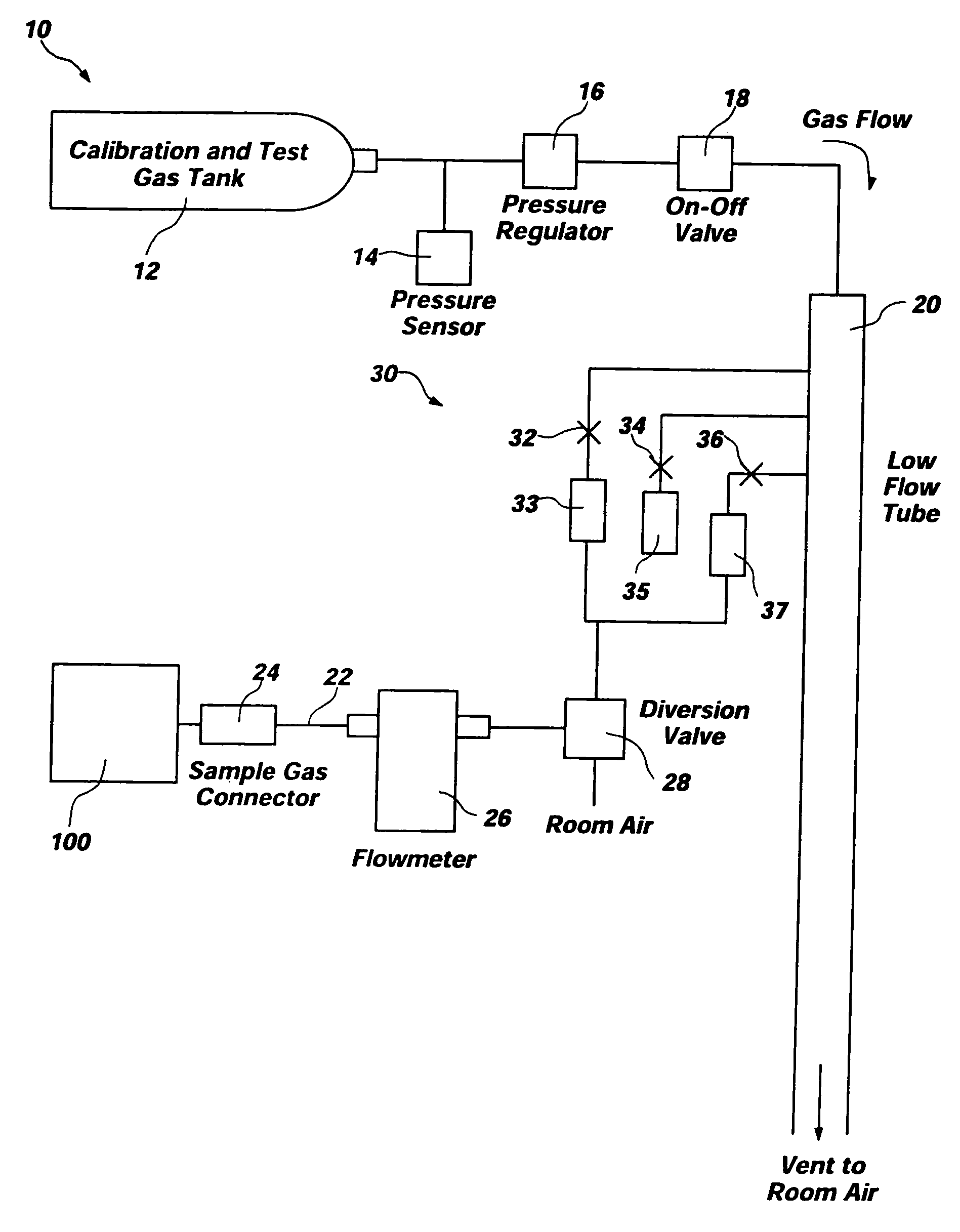
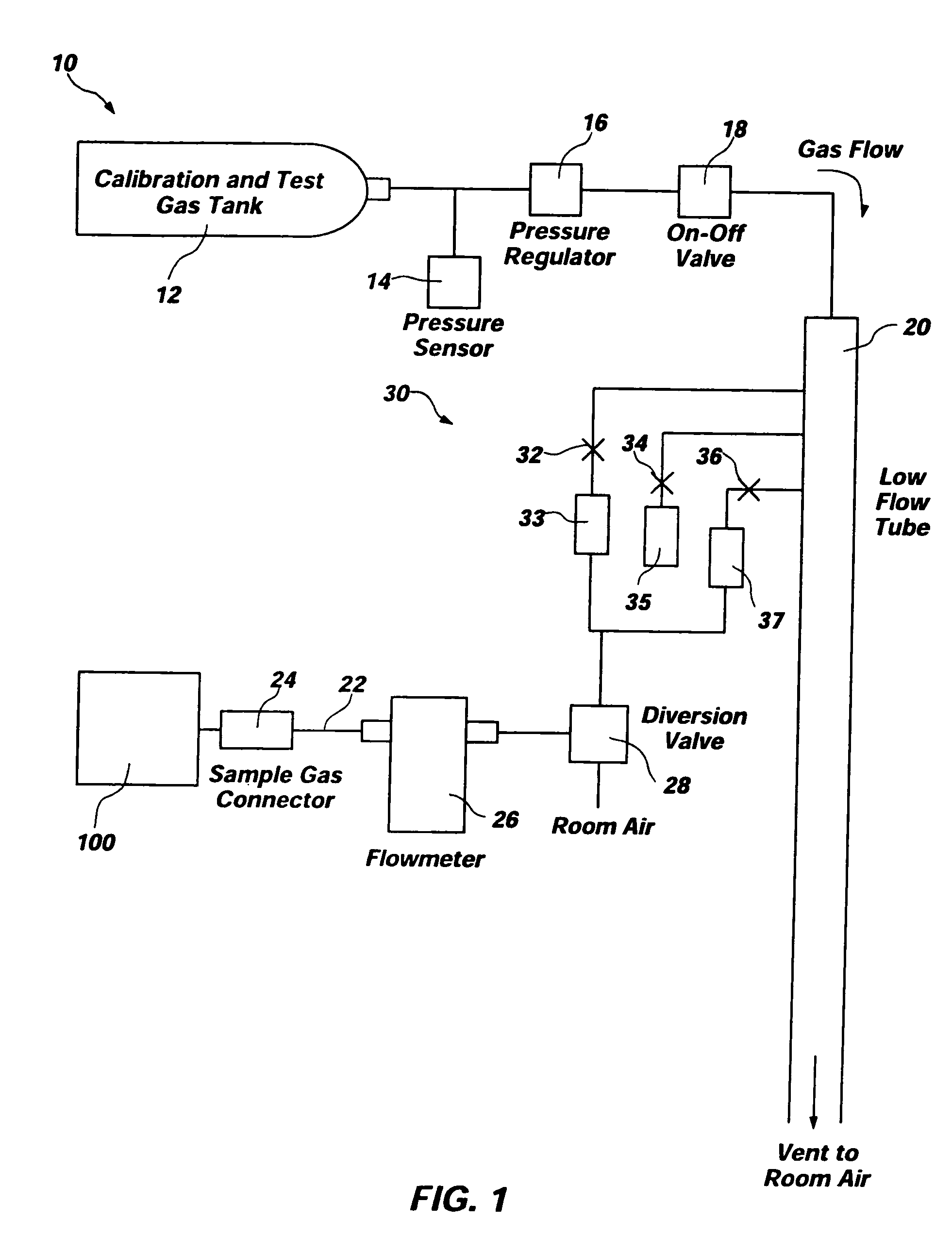
[0025]FIG. 1 depicts an exemplary embodiment of test system 10 for gas analyzers. Test system 10 comprises a “smart tank” and is configured to test or calibrate a device under test 100, such as a capnometer, other gas analyzer, or anesthesia analyzer. As depicted, test system 10 includes a tank 12 and various conduits, sensors, regulators, valves, and flow restrictors to provide a complete system for verifying that device under test 100 is functioning correctly or for calibrating device under test 100. Additionally, one or more processing elements 50 may control operation of one or more of the other elements of test system 10 and, if processing elements 50 control operation of more than one other element of test system 10, synchronize operation of the elements.

[0026] Test system10 employs a tank 12 of a known type (e.g., a conventional cylinder-type tank) which contains a precision blended calibration gas mixture for use in testing or calibrating device under test 100. The pressure...


PUM

PropertyMeasurementUnit
pressureaaaaaaaaaa
partial pressureaaaaaaaaaa
pressureaaaaaaaaaa

Abstract

A test system for assessing the performance of an analyzer for a gas or an anesthetic agent includes a source of a calibration gas mixture, a valve for controlling flow of gas from the source, a low-pressure tube, a sample tube in communication with the low-pressure tube, and a connector for assembling the analyzer to the test system. The test system may also include a valve for diverting ambient air into the sample tube instead of the calibration gas mixture. Additionally, the test system may include one or more of a barometer, a flow meter, an analyzer for gas or anesthetic agents, a flow restriction system, and a relatively high pressure source. Methods for testing analyzers are also disclosed.

Description

CROSS-REFERENCE TO RELATED APPLICATIONS [0001] This application is a continuation of PCT International Application No. PCT / US2003 / 040836, filed Dec. 22, 2003, designating the United States of America, and published, in English, as PCT International Publication No. WO 2004 / 059317 A1 on Jul. 15, 2004, which application claims priority to U.S. Provisional Application No. 60 / 435,906, filed Dec. 20, 2002, the entire contents of each of which are hereby incorporated herein by this reference.TECHNICAL FIELD [0002] The present invention relates to methods and systems for accurately assessing the performance of gas analyzers, such as carbon dioxide monitors and sensors. BACKGROUND ART [0003] Clinical practice standards for delivering anesthesia to a patient require that the concentration of carbon dioxide (CO2) expired by the patient be monitored during all anesthetic procedures in which the respiratory drive of the patient (i.e., the patient's ability to breathe on his or her own) may be im...

Claims


Application Information

Patent Timeline
Patent Type & Authority Applications(United States)
IPC IPC(8): G01N7/00G01N33/00
CPCG01N1/2247G01N2001/2244G01N35/00712G01N33/0006
Inventor ORR, JOSEPH A.KOFOED, SCOTT
Owner AXON MEDICAL INC
Learn More