Device employing magnetic flux to measure the level of fluid in a tank

Inactive Publication Date: 2006-01-05
DE AMERTEK
View PDF10 Cites 43 Cited by
  • Summary
  • Abstract
  • Description
  • Claims
  • Application Information

AI Technical Summary

Benefits of technology

[0008] The opposite end of the pivot pin has an enlarged head which retains the pivot pin into the stationery housing member. Mounted on either the rotor or the housing is the pair of magnets oriented with like poles directed generally toward each other as described above. Mounted on the other of the rotor and housing is a Hall effect sensor for measuring the strength and direction of magnetic flux. When the first and second housing members are assembled to each other and retained together by the pin, the Hall effect sensor is positioned between the two magnets and moves toward one of the magnets as the float in the fuel tank rises and moves toward the second magnet as the float in the tank drops.
[0009] An inner housing member made of plastic surrounds the Hall effect sensor and any other electronics in the device and insulates the electrical components retained therein. Also molded into the housing is a lead frame, which includes a planar panel oriented perpendicular to the pivot pin and having a hole therethrough through which the pivot pin passes. The planar panel of the lead frame is formed at the end of an elongate strap that extends to the exterior of the housing where it can be attached by a wire to the body of the vehicle in which the tank is located. Since the second end of the pivot pin extends through the hole in the planar panel of the ground lead, the electrical contact between the plate, and the pin, the

Problems solved by technology

The surfaces of the device used to measure the level of the fuel in a tank are subject to the corrosive effects of the chemicals that make up the fuel

Method used


Image

  • Device employing magnetic flux to measure the level of fluid in a tank
  • Device employing magnetic flux to measure the level of fluid in a tank
  • Device employing magnetic flux to measure the level of fluid in a tank

Examples


Embodiment Construction

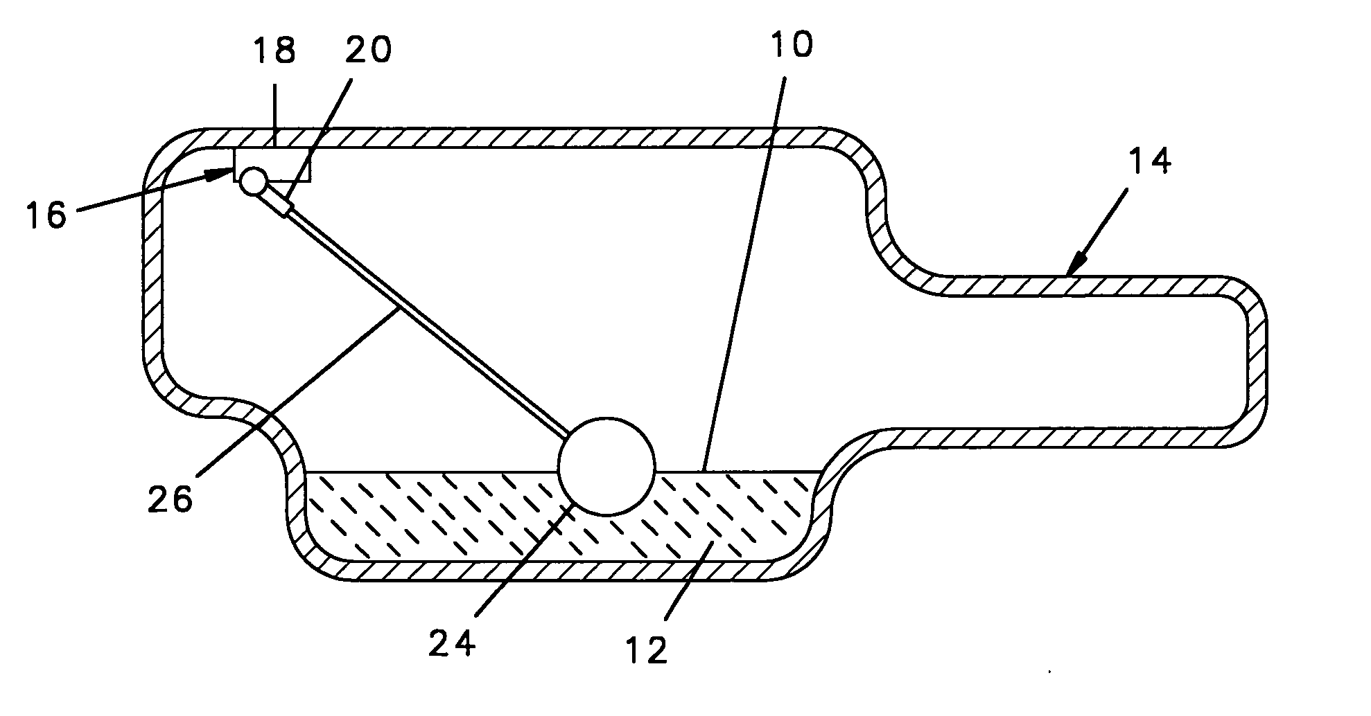
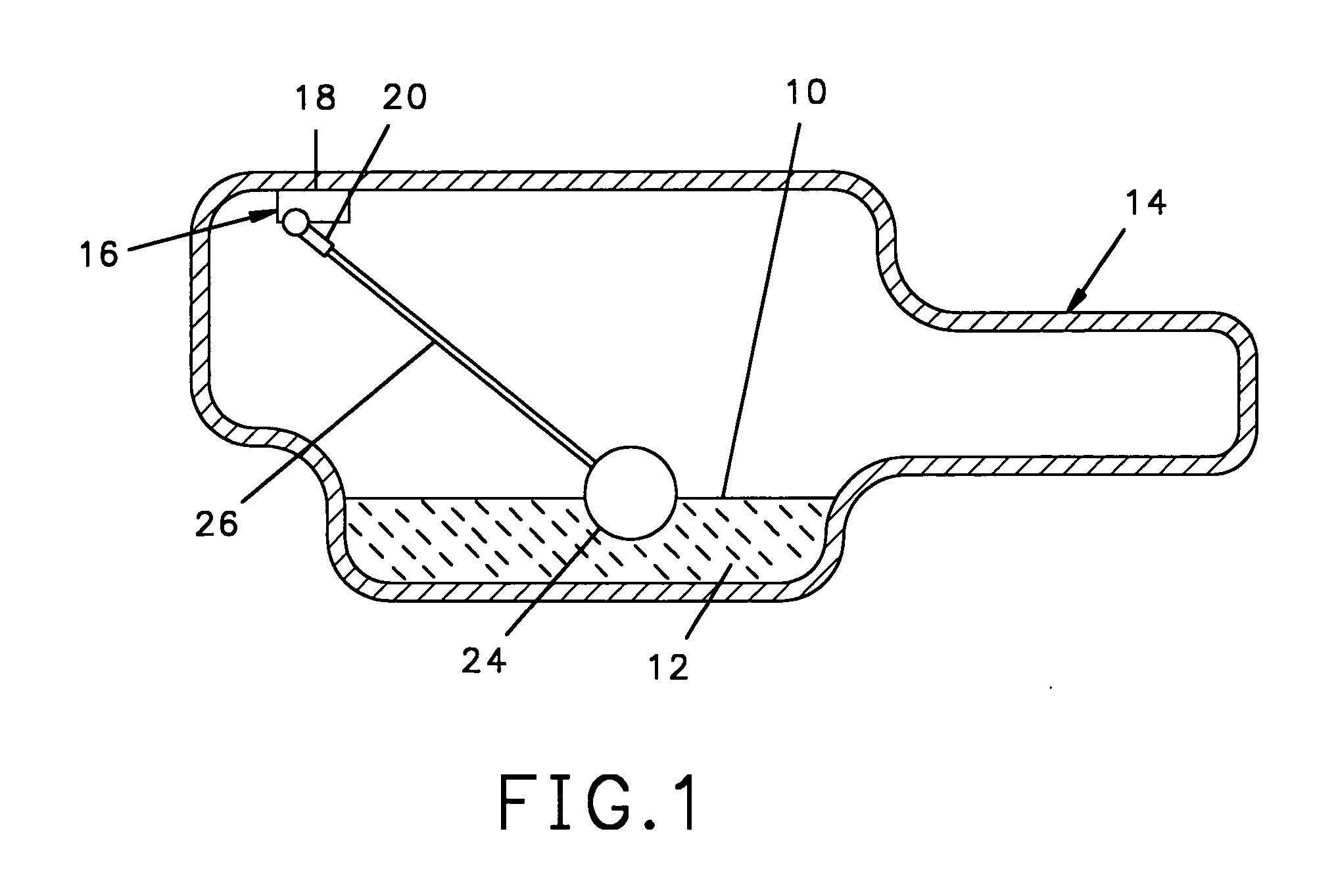
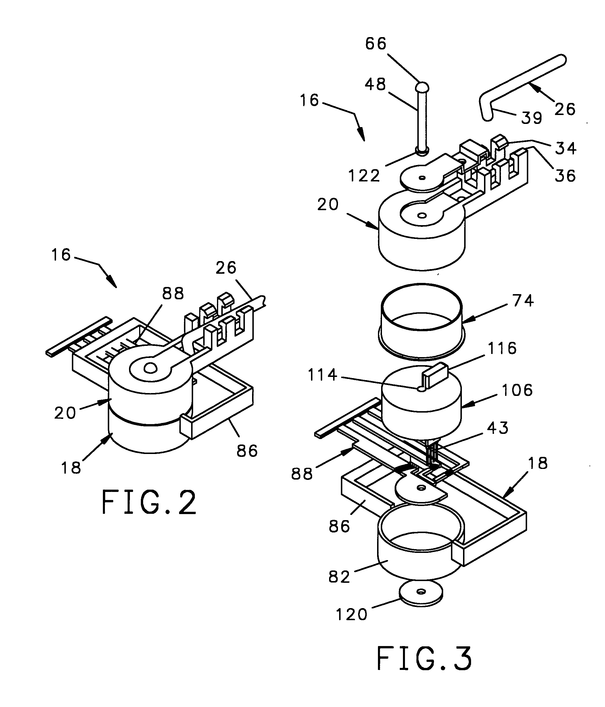
[0035] To measure the level 10 of fuel 12 in a tank 14 of a motor vehicle, not shown, a fuel level sensor 16 in accordance with the invention is provided that includes a stationary housing 18 and a rotor 20. The rotor 20 is rotated with respect to the housing by the movement of a float 24 attached to the rotor 20 by means of a rod 26.

[0036] It has been found that the rod 26 is preferably made of steel rather than plastic or wood, however, a steel rod 26 is subject to a static electricity built up along the surface thereof. Government regulations require that the liquid fuel in a fuel tank be grounded to prevent an electrostatic buildup. Fuel level sensors in accordance with the prior art employ a potentiometer including a resistor card and a moveable wiper to provide a signal that is responsive to the changes in the fuel level in the tank, and a second wiper was provided on such sensors for grounding the metal rod connecting the sensor to the float.

[0037] Referring to FIGS. 3, 5, ...


PUM


Abstract

A fuel level sensor has a rotor with two magnets mounted for rotation therewith, the magnets spaced from one another and with like poles directed toward one another. A Hall effect sensor on the housing is positioned between the two magnets such that increasing the volume of fluid in the tank moves one magnet toward the sensor and decreasing the volume in the tank moves the other magnet toward the sensor. A metal sleeve around the magnets protects the parts from interference from magnetic material in the fuel. A static discharge path is provided from a metal rod connecting a float, a plate contracting the rod, and a pivot pin retaining the rotor to the housing, and a ground connector in contact with the pivot pin.

Description

[0001] The present invention relates to a fuel level detector, the parts of which are protected against the corrosive effects of the fuel. BACKGROUND OF THE INVENTION [0002] It is necessary to measure as accurately as possible, the level of fuel or the volume of fuel in a fuel tank of a vehicle. Typically, the fuel level or volume is measured by using a float connected to arm and a wiper for wiping a contact pattern on a variable resistor. The float moves with the level of the fuel and as the float moves, the arm causes the wiper to move across an arcuate wiper track changing the resistance of the resistor in response to changes in the level of the liquid or the volume in the tank. [0003] The surfaces of the device used to measure the level of the fuel in a tank are subject to the corrosive effects of the chemicals that make up the fuel. Methanol is particularly corrosive. Over the course of time, the corrosion of critical elements will result in inaccuracies in the measurements tak...

Claims


Application Information

Patent Timeline
IPC IPC(8): G01F23/36
CPCG01F23/38
Inventor JAMNIA, MOHAMMAD ALICHEN, JACK
Owner DE AMERTEK
Why Eureka
Try Eureka