Turbine blade for monitoring blade vibration

Active Publication Date: 2006-01-05
SIEMENS ENERGY INC
View PDF8 Cites 55 Cited by
  • Summary
  • Abstract
  • Description
  • Claims
  • Application Information

AI Technical Summary

Problems solved by technology

These dynamic conditions can lead to blade vibration, which is an appreciable cause of excitation failure in turbo-machinery.
However, such monitoring and evaluation is both costly and time inefficient.
However, these painted targets are problematic because they cannot detect motion in

Method used


Image

  • Turbine blade for monitoring blade vibration
  • Turbine blade for monitoring blade vibration
  • Turbine blade for monitoring blade vibration

Examples


Embodiment Construction

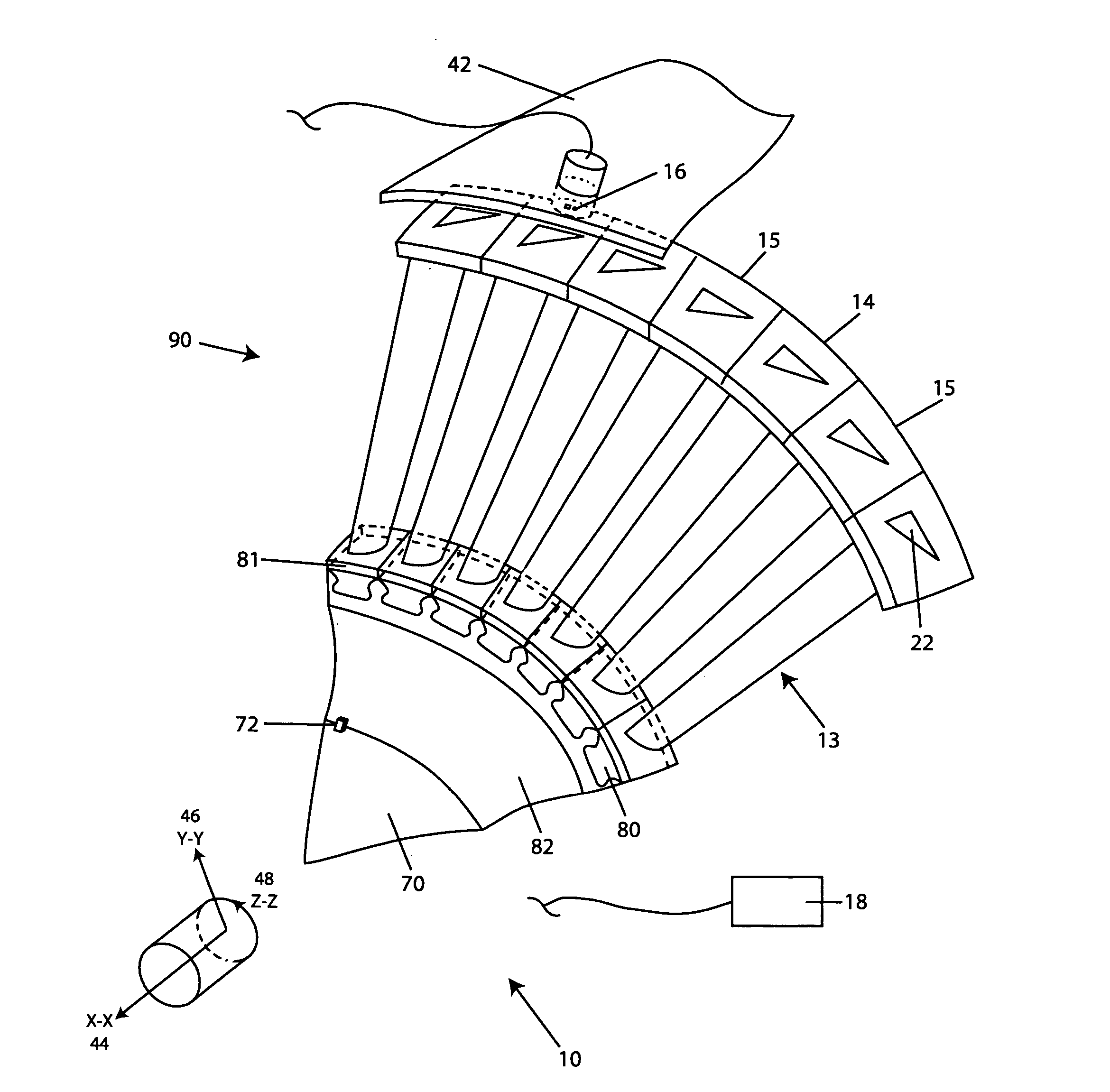
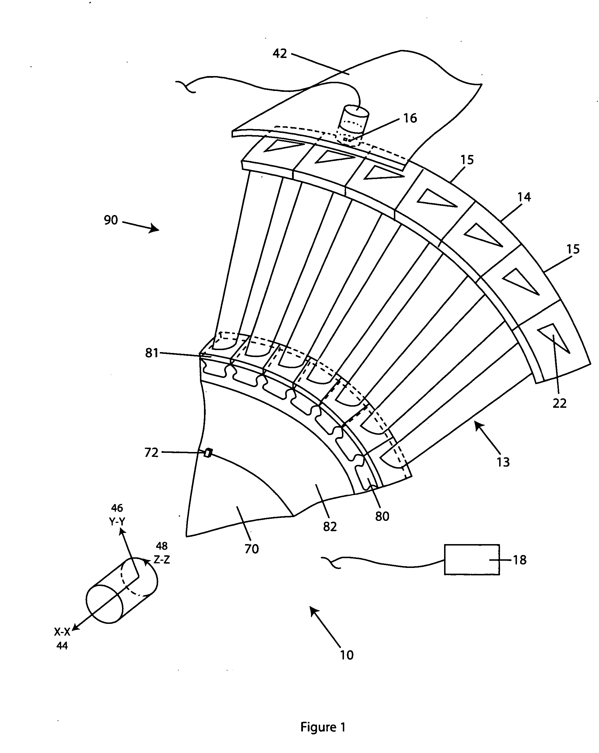
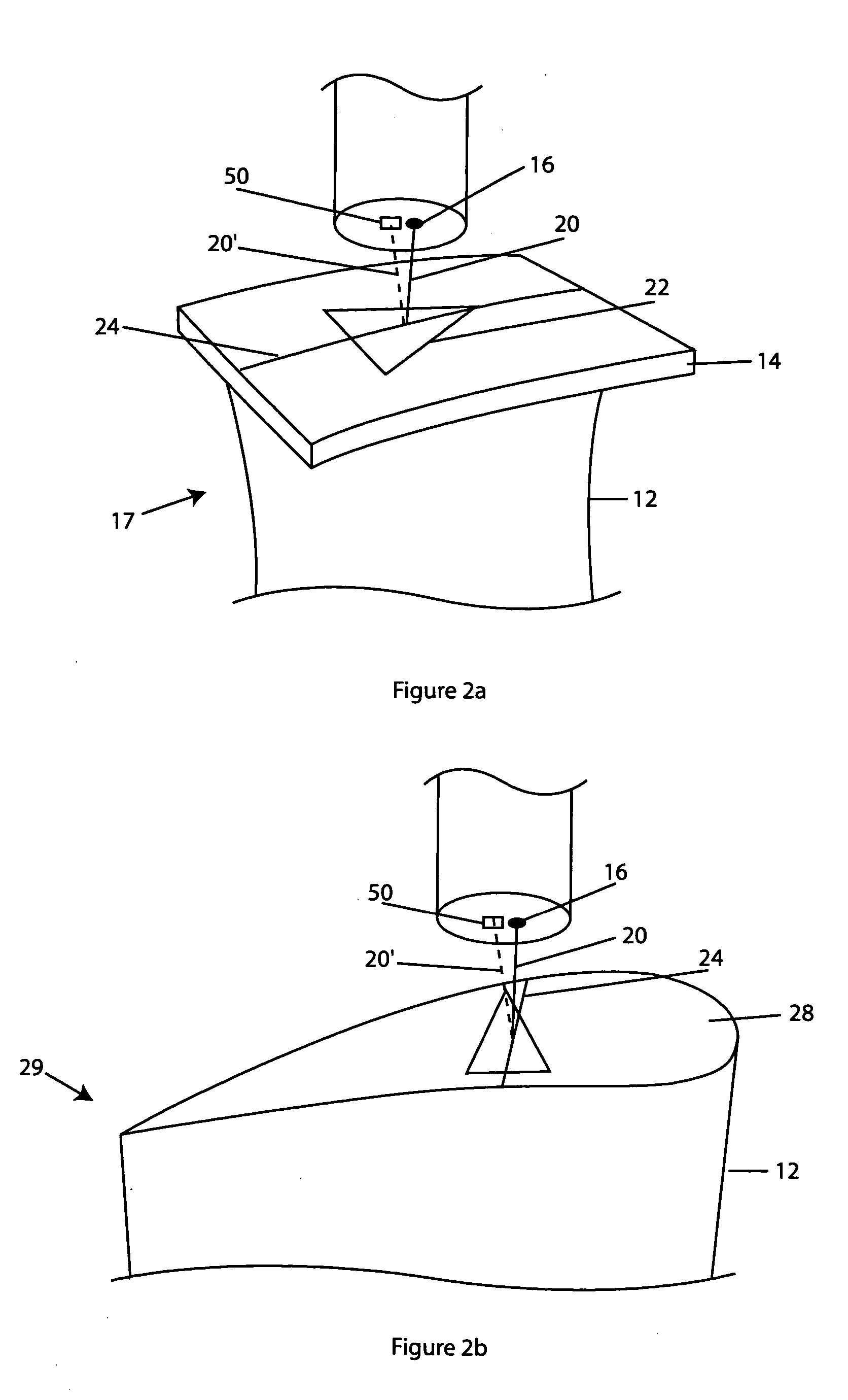
[0017] The monitoring system 10 described herein employs some basic concepts. For example, one concept relates to a monitoring system 10 that measures the frequency and amplitude of turbine blade 17 vibration, and monitors the vibration of the turbine blade 17. Another concept relates to a turbine blade 17 adapted for used with the monitoring system 10. Yet another concept relates to the processing of turbine blade 17 vibration signal information into usable computer output 60.

[0018] The present invention is disclosed in context of use as a monitoring system 10 within a combustion turbine engine for monitoring vibration of rotating turbine blades 17. The principles of the present invention, however, are not limited to use within combustion turbine engines or to monitor vibration of rotating turbine components. For example, the monitoring system 10 can be used in other operational monitoring environments to measure blade turbine 17 vibration, such as steam turbines, aero-thermal air...


PUM


Abstract

The claimed invention provides a blade vibration measuring system comprising a blade, a transmitter, a target with non parallel edges located on the blade shroud and a receiver. The present invention also provides a blade adapted for measuring blade vibration. Furthermore, the claimed invention provides a method for monitoring blade vibration.

Description

FIELD OF INVENTION [0001] The present invention relates generally to blade vibration monitoring and, more particularly, to blade vibration monitoring of a shrouded turbine blade. BACKGROUND OF INVENTION [0002] Turbo-machinery engines, such as combustion turbine engines, contain rotating blades in a compressor section and rotating blades in a turbine section. The blades are generally arranged circumferentially in rows with each row being comprised of a plurality of blades. Typical geometries include free standing blades (i.e. blades that do not contact adjacent blades) or shrouded blades (i.e. blades that do contact adjacent blades). [0003] During normal engine operation, the rotating blades are exposed to excitation due to dynamic conditions in the engine such as flow induced vibration and nozzle effects. These dynamic conditions can lead to blade vibration, which is an appreciable cause of excitation failure in turbo-machinery. [0004] A known means to avoid excitation failure is by...

Claims


Application Information

Patent Timeline
IPC IPC(8): G01N29/00
CPCG01H1/003G01N2291/2693G01N29/2418
Inventor TWERDOCHLIB, MICHAEL
Owner SIEMENS ENERGY INC
Why Eureka
Try Eureka