Die casting machine

a technology of die casting machine and injection piston, which is applied in the direction of manufacturing tools, foundry patterns, and moulding apparatus, etc., can solve the problems of early abrasion of parts, influence on and cavity generation, so as to improve the useful life of the sleeve and the injection piston

Active Publication Date: 2006-01-05
TAIHO INDUSTRIES CO LTD
View PDF2 Cites 13 Cited by
  • Summary
  • Abstract
  • Description
  • Claims
  • Application Information

AI Technical Summary

Benefits of technology

[0007] In view of the foregoing, the present invention intends to provide a die casting machine including lubricant oil feeding means which improves the useful life of the sleeve and the injection piston as compared with the prior art.

Problems solved by technology

However, with either lubricant oil feeding means, it is difficult to cause the lubricant oil to be spread around the both peripheral surfaces from the clearance between the end face of the sleeve and the end face of the injection piston, causing an early abrasion of portions which are not covered by the lubricant oil or which require time until they are covered by the lubricant oil to influence upon the useful life of the sleeve and the injection piston.
To overcome above problem, it may be contemplated to increase the supply of the lubricant oil, but when the lubricant oil is supplied than is required, there results a disadvantage that an excess amount of lubricant oil reacts with molten metal to be gasified during a pouring operation to cause cavities to be generated or to cause an imperfect plating.

Method used


Image

  • Die casting machine
  • Die casting machine
  • Die casting machine

Examples


Embodiment Construction

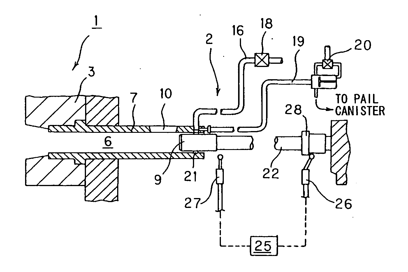
[0017] An embodiment of the invention shown in the drawings will now be described. There is shown a compact size die casting machine 1, to which lubricant oil feeding means 2 according to the invention is applied. The die casting machine 1 comprises a fixed die 3 acting as a first die which is mounted on a stationary frame, not shown, and a movable die 4 acting as a second die (see FIG. 5) which is driven for reciprocatory motion toward and away from the fixed die 3, and when the movable die 4 is brought into abutment against the fixed die 3, a closed casting space 5 (see FIG. 5) is defined therebetween.

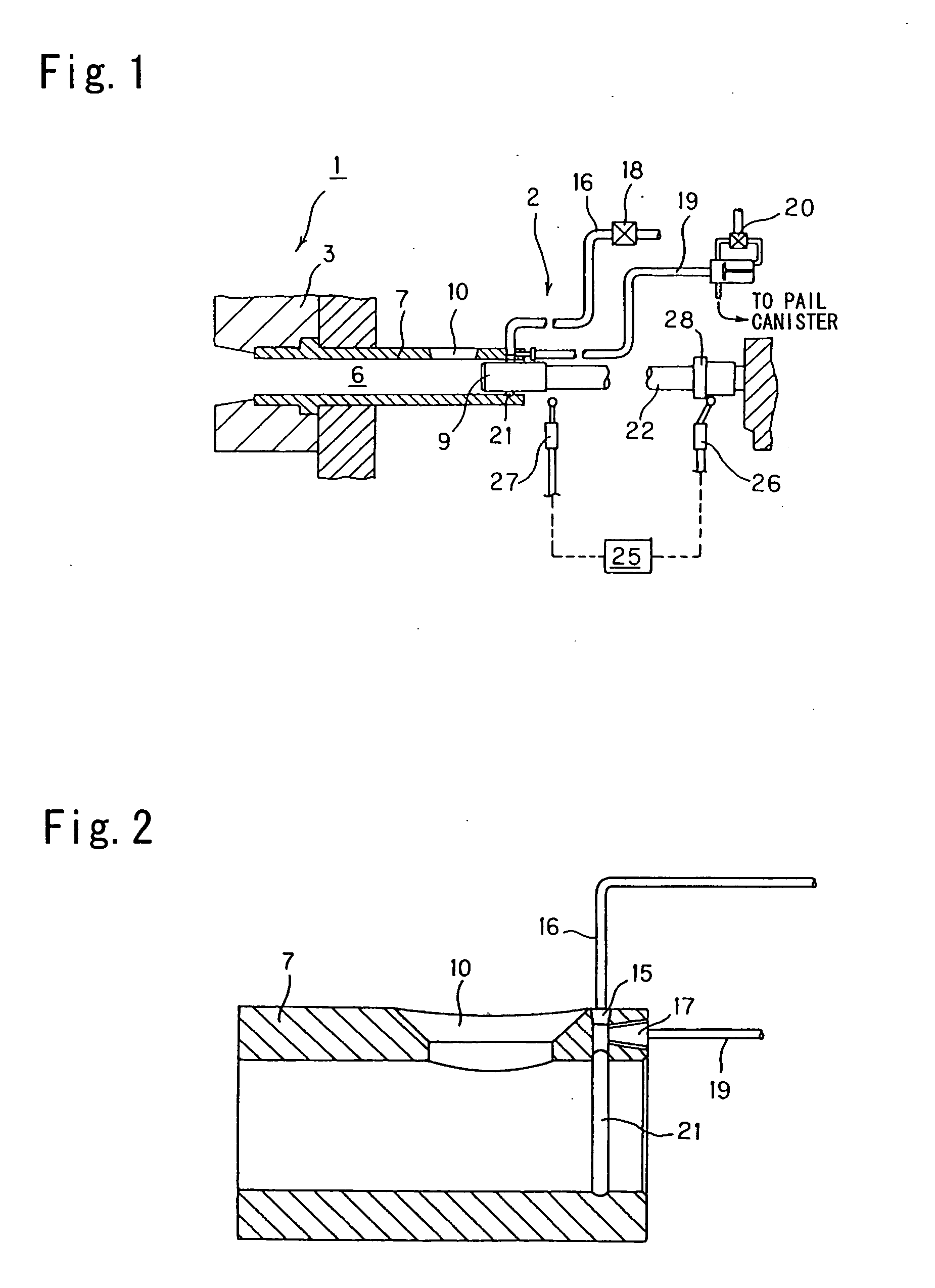
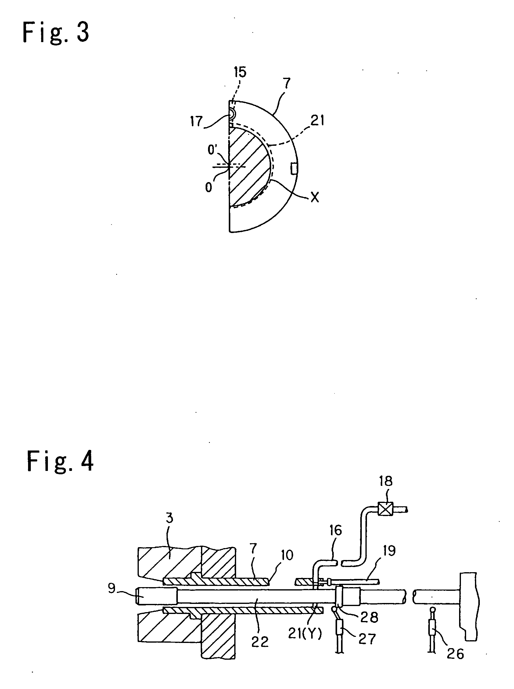
[0018] A sleeve 7 is disposed in the fixed die 3 and communicates with the casting space 5 and is internally formed with a sprue runner 6. An injection piston 9 is slidably disposed within the sleeve 7 and is driven for reciprocatory motion therein by drive means, not shown.

[0019] At its one end, the sleeve 7 is notched in its upper portion to provide a gate 10 which allows molten ...


PUM

PropertyMeasurementUnit
sizeaaaaaaaaaa
depthaaaaaaaaaa
lengthaaaaaaaaaa

Abstract

Lubricant oil feeding means 2 of a die casting machine 1 comprises a lubricant oil feed passage 19 for feeding a lubricant oil into a clearance between the inner peripheral surface of a sleeve 7 and the outer peripheral surface of an injection piston 9, a lubricant oil feed valve 20 for opening or closing the lubricant oil feed passage, an air feed passage 16 for feeding air into a clearance between the inner peripheral surface of the sleeve and the outer peripheral surface of the injection piston, and an air feed valve 18 for opening and closing the air feed passage, and an arrangement is such that the lubricant oil feed valve is initially opened to feed the lubricant oil into the clearance between the sleeve and the injection piston and the air feed valve is then opened to pump the lubricant oil by the air. It is possible to spread the lubricant oil extensively and quickly, and accordingly, the useful life of the sleeve and the injection piston can be improved with a reduced quantity of lubricant oil. The generation of gas as a result of a reaction with molten metal within the sleeve can also be suppressed, thus allowing the occurrence of a casting cavity to be prevented and the quality of a product to be improved.

Description

FIELD OF THE INVENTION [0001] The present invention relates to a die casting machine, and more particularly, to an improvement of lubricant oil feeding means which feeds a lubricant oil into a clearance between the inner peripheral surface of a sleeve and the outer peripheral surface of an injection piston. DESCRIPTION OF THE PRIOR ART [0002] A die casting machine is well known in the art which comprises at least two or a first and a second die which are disposed in abutment against each other to define a casting space therebetween, a sleeve mounted on the first die and communicating with the casting space, an injection piston slidably disposed within the sleeve for injecting molten metal fed into the sleeve into the casting space, drive means for reciprocating the injection piston, and lubricant oil feeding means for feeding a lubricant oil into a clearance between the inner peripheral surface of the sleeve and the outer peripheral surface of the injection piston. [0003] An arrange...

Claims


Application Information

Patent Timeline
Patent Type & Authority Applications(United States)
IPC IPC(8): B22D17/08B22C3/00
CPCB22D17/2038B22D17/2023
Inventor SHINKI, YOSHIYUKIIZUTSU, ISAMUNISHIYAMA, AKIRANISHIYAMA, KAZUKO
Owner TAIHO INDUSTRIES CO LTD
Why Eureka
Try Eureka