Tool attachment and organizer system and methods

a tool and organizer technology, applied in the field of tool storage and organization devices, can solve the problems of deficiency of peg boards and other storage devices of the past, general limitation of the position of the peg, and limited support of the peg, so as to achieve uniform and aesthetically attractive appearance

Inactive Publication Date: 2006-01-05
SHOLEM STEVEN
View PDF6 Cites 22 Cited by
  • Summary
  • Abstract
  • Description
  • Claims
  • Application Information

AI Technical Summary

Benefits of technology

[0043] It is to be understood that the tray may be a lower tray of a pair of trays. Alternatively, the tray may be the upper tray. The permanent magnet(s) may fit snugly in the tray into which they are received. The tray may have a base and a surrounding wall to receive the permanent magnets therein. When in use the magnet bar may be placed with the tray opening facing away from the user and towards a magnetically attractive sheet so as to present a closed side of the tray for a more uniform and aesthetically attractive appearance.

Problems solved by technology

The peg boards and other storage devices of the past are deficient, on the other hand, because they limit the orientations of stored tools and the position of the tools on a support substrate.
This is because pegs are limited to being supported in pre-drilled holes.
If a user wants to move the mounting pegs closer together or wants to group the tools by tool type, he or she is generally limited to the positions provided by the locations of the pre-drilled holes or the other incremental mounting structure.
Even in past devices in which a continuous strip of magnetic material is attached to the support substrate, the tools are limited to mounting in positions that have been predetermined by the placement of the strip of material.
The past devices are also deficient in providing a very durable hard finish to a peg board.
Therefore, the peg boards of the past are vulnerable to marring during storing and retrieving of tools.
Even if the doors and drawers are left open, the compact nature of tool boxes and cabinets generally causes at least some of the tools in the boxes or cabinets to be layered and hidden from view.
That is, the tool boxes and cabinets of the past are deficient because they generally require a user to open and close drawers and to dig for tools during their search for a particular tool.

Method used


Image

  • Tool attachment and organizer system and methods
  • Tool attachment and organizer system and methods
  • Tool attachment and organizer system and methods

Examples


Embodiment Construction

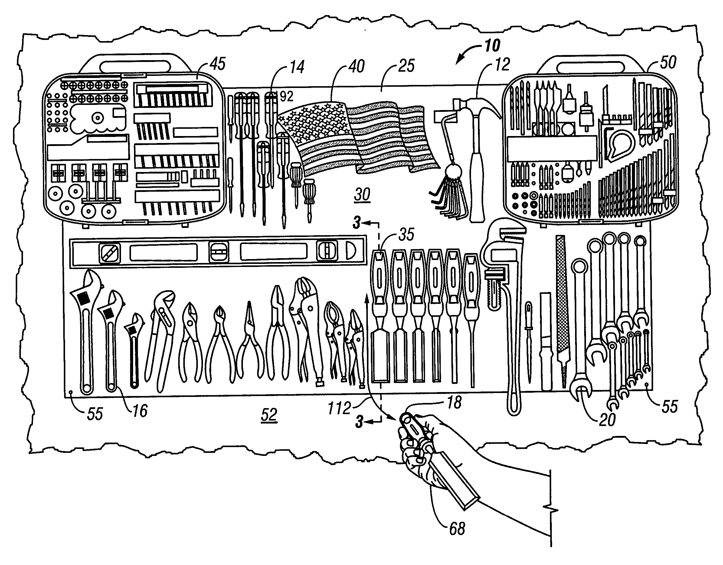
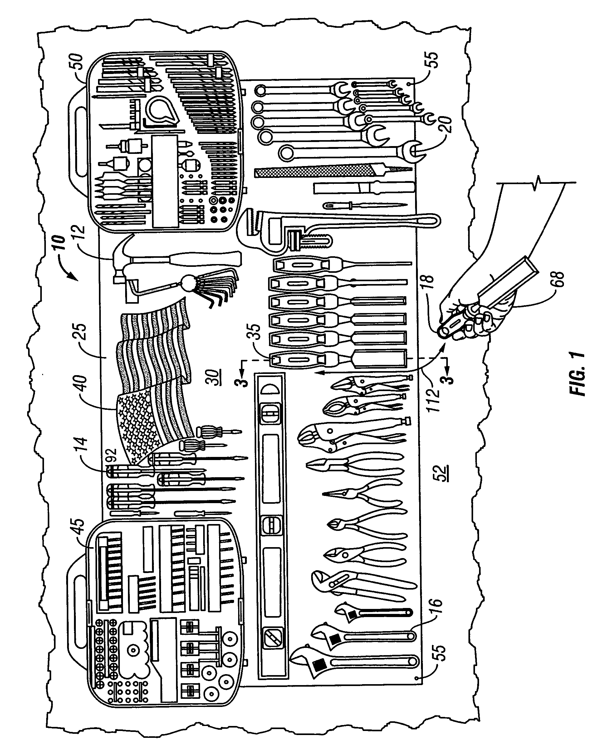
[0072] As discussed above, embodiments of the present invention relate to a tool organizer system 10 for storing and organizing a set of tools of which tools 12, 14, 16, 18, 20 are examples. As shown in FIG. 1, the system 10 includes a flat sheet 25 of magnetically attracted material. This material typically is made of a sheet of metal, such as ferrous metal. However, the thin sheet 25 could also comprise a composite with metal material dispersed in the sheet or a lamination with a thin magnetically attracted sheet in a front position among the laminants. The flat sheet of material includes a front face 30 for supporting the tools including 12, 14, 16, 18, 20. A position indicator as shown at 35 is provided for each of the tools to be supported on the front face 30. These position indicators 35 can take any of many forms. By way of example and not by way of limitation, the position indicators 35 can include adhesive backed decals. Other ways of providing the position indicators 35 i...


PUM


Abstract

A tool organizer system has a flat sheet of magnetically attracted material that attracts magnets attached to tools to support the tools on the flat sheet. The system includes position indicators that can be attached at any orientation and position on the flat sheet. The system can be provided as a kit with one or more components. A method of organizing a set of tools provides for efficient use of space and clear association between a tool and a previously selected position and avoids loss of tools by placing them in previously selected positions. A method of making a tool organizer system includes making the system in accordance with requests from a customer. The tool organizer system includes a kitchen tool organizer system that has a container with at least one magnetically attractive side and a handle, allowing the container to retain kitchen tools within the container and magnetically on the side. Attachment tools may include a fastener attachment tool that couples to a tool and provides magnetic force and a magnetic bar coupled to a tool organizer to allow metal tools to be coupled to the bar.

Description

CROSS REFERENCE TO RELATED APPLICATIONS [0001] This application is a continuation-in-part of the earlier U.S. patent application Ser. No. 10 / 465,412, filed by Steven Sholem on Jun. 18, 2003, entitled “TOOL ORGANIZER SYSTEM AND METHODS,” now pending, the disclosure of which is hereby incorporated entirely herein by reference. This application further claims priority to U.S. Provisional Patent Application Ser. No. 60 / 601,522, filed by Steven Sholem on Aug. 13, 2004, entitled “TOOL ORGANIZER SYSTEM AND METHODS”, to U.S. Provisional Patent Application Ser. No. 60 / 664,857, filed by Steven Sholem on Mar. 23, 2005, entitled “MAGNETIC KITCHEN UTENSIL / TOOL HOLDER SYSTEM”, and to U.S. Provisional Patent Application Ser. No. 60 / 678,966, filed by Steven Sholem on May 12, 2005, entitled “A MAGNETIC AND NON-MAGNETIC FERROUS FASTENER FOR STORING AND DISPLAYING TOOLS AND OTHER OBJECTS ON A METAL SURFACE,” the disclosures of which are each hereby incorporated entirely herein by reference.BACKGROUND ...

Claims


Application Information

Patent Timeline
Patent Type & Authority Applications(United States)
IPC IPC(8): A47F7/00
CPCY10S211/01B25H3/04
Inventor SHOLEM, STEVEN
Owner SHOLEM STEVEN
Why Eureka
Try Eureka