Oven with a system for generating steam

a technology of steam generation and oven, which is applied in the direction of furnaces, domestic stoves or ranges, heating types, etc., can solve the problems of energy waste and damage to heating elements

Inactive Publication Date: 2006-01-05
WHIRLPOOL CORP
View PDF6 Cites 29 Cited by
  • Summary
  • Abstract
  • Description
  • Claims
  • Application Information

AI Technical Summary

Benefits of technology

This patent describes an appliance called an oven which has a feature for measuring how much water is inside its tank. There are two levels: one when there's no water (maximum) and another when there's very little water (minimum). When the water reaches the minimum point, it triggers a message from the oven indicating that more water needs to be added. The design also includes a mechanism that controls when the heating elements turn on or off based on the amount of water inside the tank. Additionally, the oven may have a separate pump to move the water around within the system.

Problems solved by technology

The technical problem addressed in this patent is the inefficient and potentially damaging use of water in steam generation systems for ovens, which can lead to overheating or energy wastage.

Method used


Image

  • Oven with a system for generating steam
  • Oven with a system for generating steam
  • Oven with a system for generating steam

Examples


Embodiment Construction

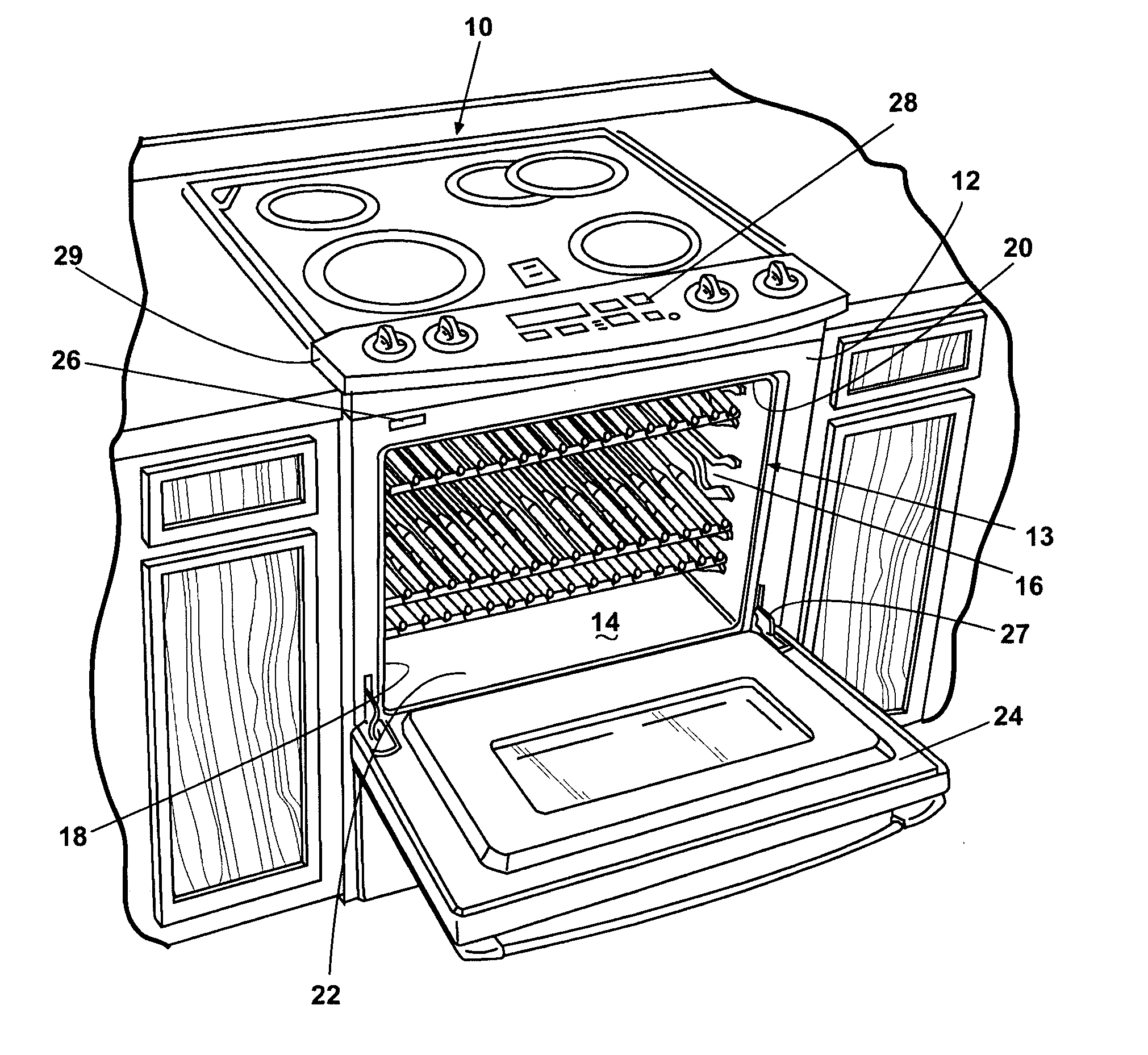
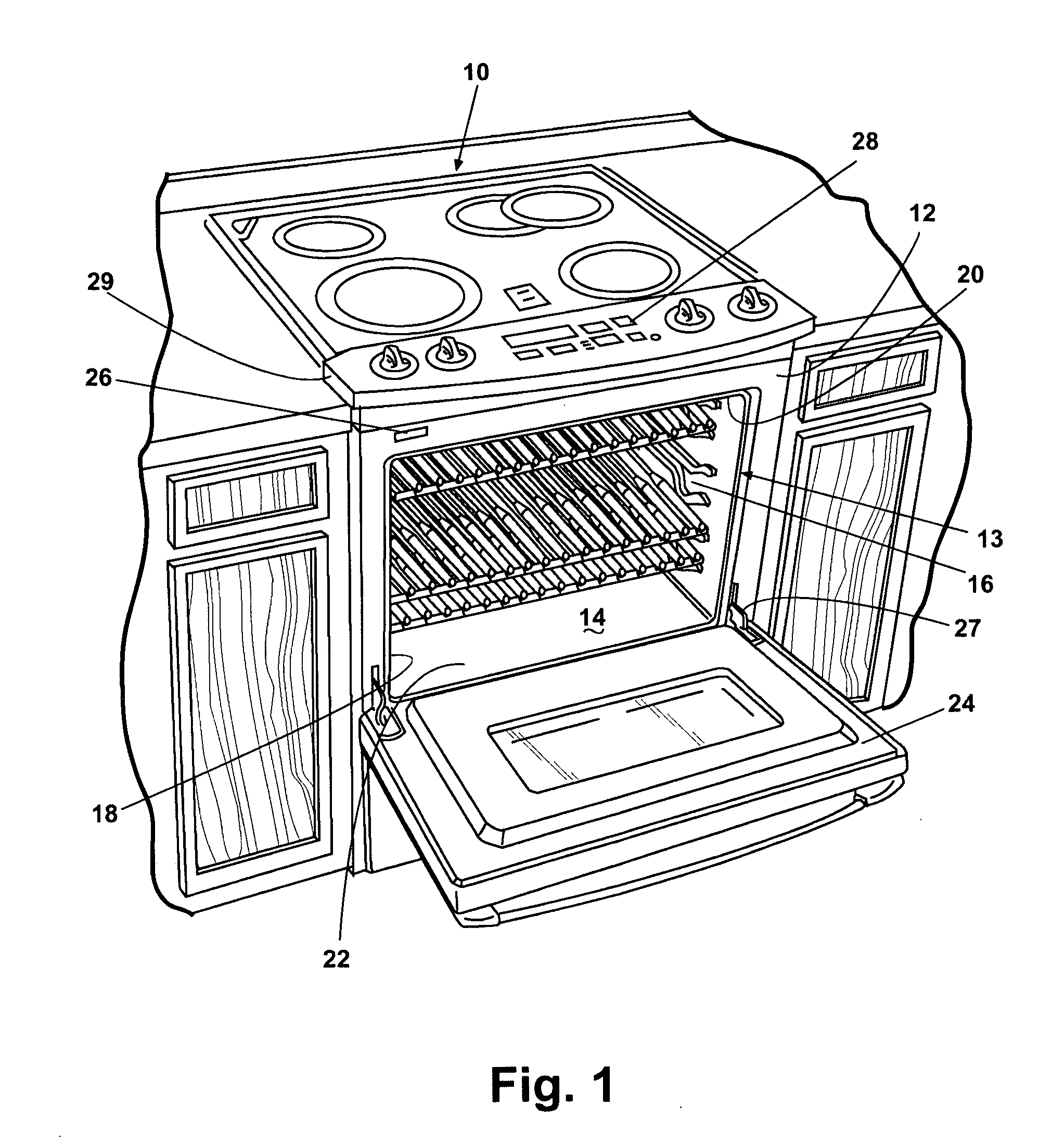
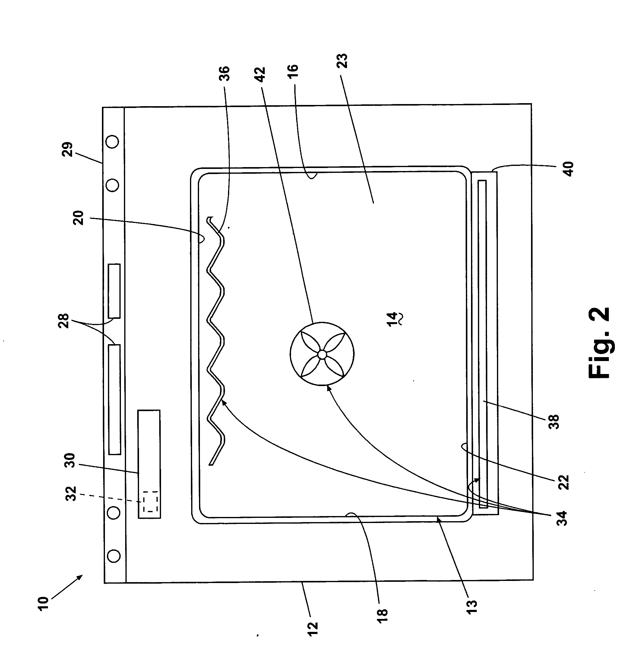
[0023] Referring now to the figures, FIG. 1 illustrates an exemplary automatic household oven 10 that can be equipped with a steam system according to one embodiment of the invention. The oven 10 comprises a cabinet 12 with an open-face housing 13 having a pair of spaced side walls 16, 18 joined by a top wall 20, a bottom wall 22, and a rear wall 23 (FIG. 2) to define an open-face cooking cavity 14. A door 24 pivotable at a hinge 27 selectively closes the cavity 14, and a sensor 26 detects an open position of the door 24 and a closed position of the door 24. When the door 24 is in the open position, a user can access the cavity 14, while the door 24 in the closed position prevents access to the cavity 14 and seals the cavity 14 from the external environment.

[0024] The oven 10 further comprises a console 29 with a control panel 28 having a user interface accessible to the user for inputting desired cooking parameters, such as temperature and time, of manual cooking cycles or for sel...


PUM


Abstract

An oven comprises a housing defining a cooking cavity, a steam generator defining a chamber and having an evaporation element located in the chamber for generating steam that is introduced into the cooking cavity, and a water reservoir in fluid communication with the chamber and positioned relative to the chamber to supply water to the chamber to at least a minimum level at which the water completely immerses the evaporation element. Further, the steam generator can have a top defining an upper extent of the chamber, and the water reservoir can have a top positioned relative to the chamber such that the water reservoir top is vertically below the steam generator top.

Description


Claims


Application Information

Patent Timeline
Owner WHIRLPOOL CORP
Why Eureka
Try Eureka