Vapor deposition method and apparatus

a technology of vapor deposition and evaporation position, which is applied in the direction of vacuum evaporation coating, chemical vapor deposition coating, coating, etc., can solve the problems of partially accelerating deterioration in the film, misalignment of firm-forming position, etc., to prevent misalignment of evaporation position, increase cooling effect, and stabilize product quality

Active Publication Date: 2009-01-15
HITACHI DISPLAYS +1
View PDF6 Cites 143 Cited by
  • Summary
  • Abstract
  • Description
  • Claims
  • Application Information

AI Technical Summary

Benefits of technology

[0031]According to the aspects of the invention, in vacuum vapor deposition of the so-called in-line system, a cooling board placed inside of a vacuum chamber is located proximal to a carrier or the frame of an evaporation mask during transfer thereof and film formation. This accordingly prevents, more than previous, radiant heat coming from the high-temperature evaporation source from being transmitted to the substrate, the evaporation mask, and the carrier. At the same time, the evaporation mask and the carrier can be cooled by radiation to the cooling board. If transfer rollers are each provided with the cooling capability, the cooling effect can be increased to a further extent.
[0032]As such, any possible temperature increase can be suppressed for the components, i.e., the substrate, the evaporation mask, and the carrier, thereby being able to prevent misalignment of evaporation p

Problems solved by technology

As a result, if the apparatus is put in the long-term continuous operation, the firm-forming position is misaligned with respect to pixels between before and after the film formation.
Su

Method used


Image

  • Vapor deposition method and apparatus
  • Vapor deposition method and apparatus
  • Vapor deposition method and apparatus

Examples


first embodiment

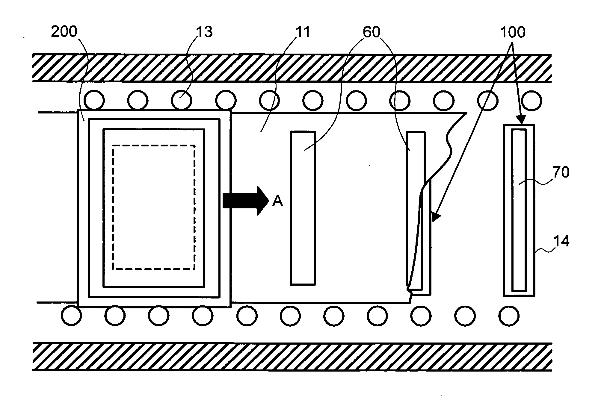
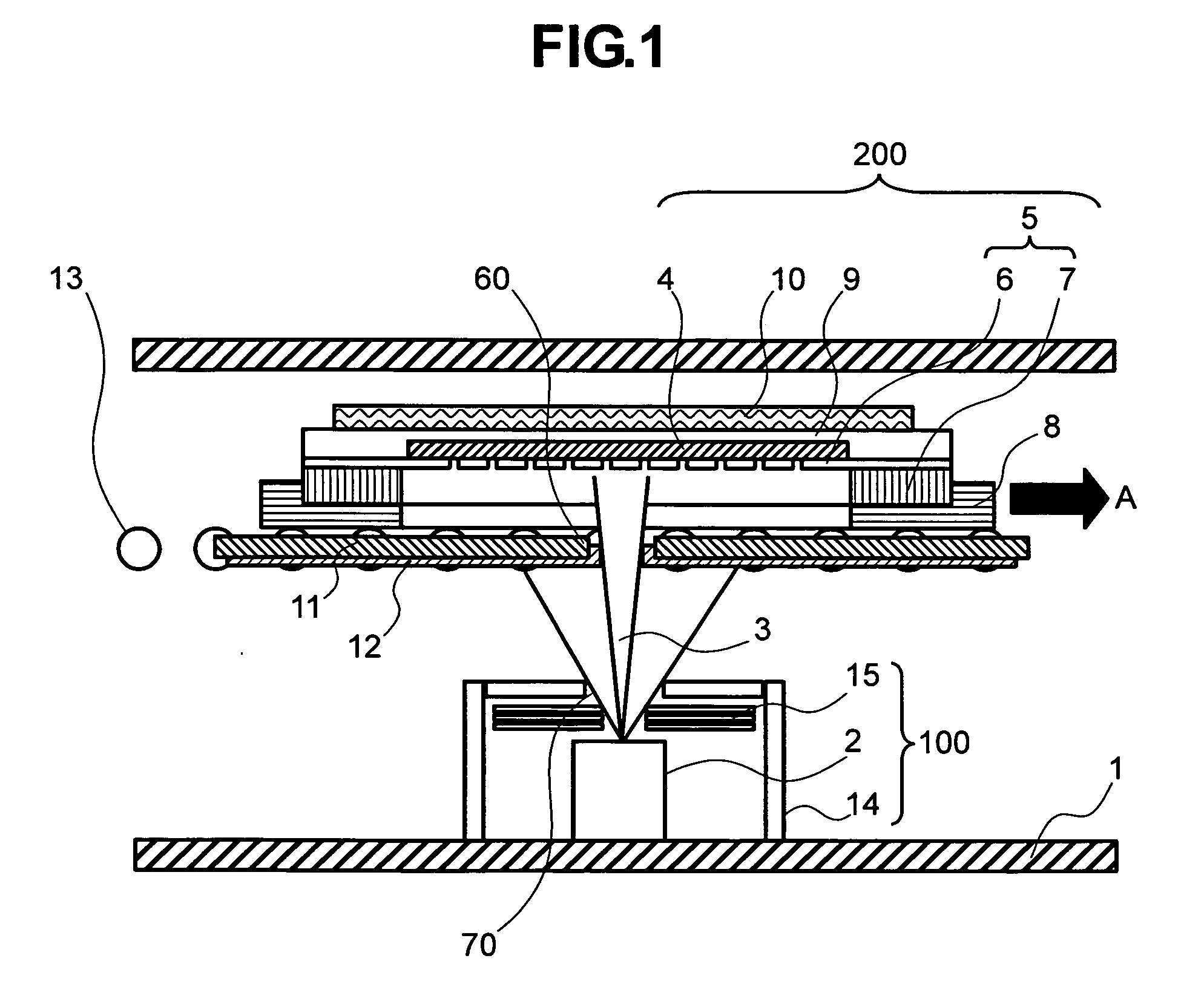
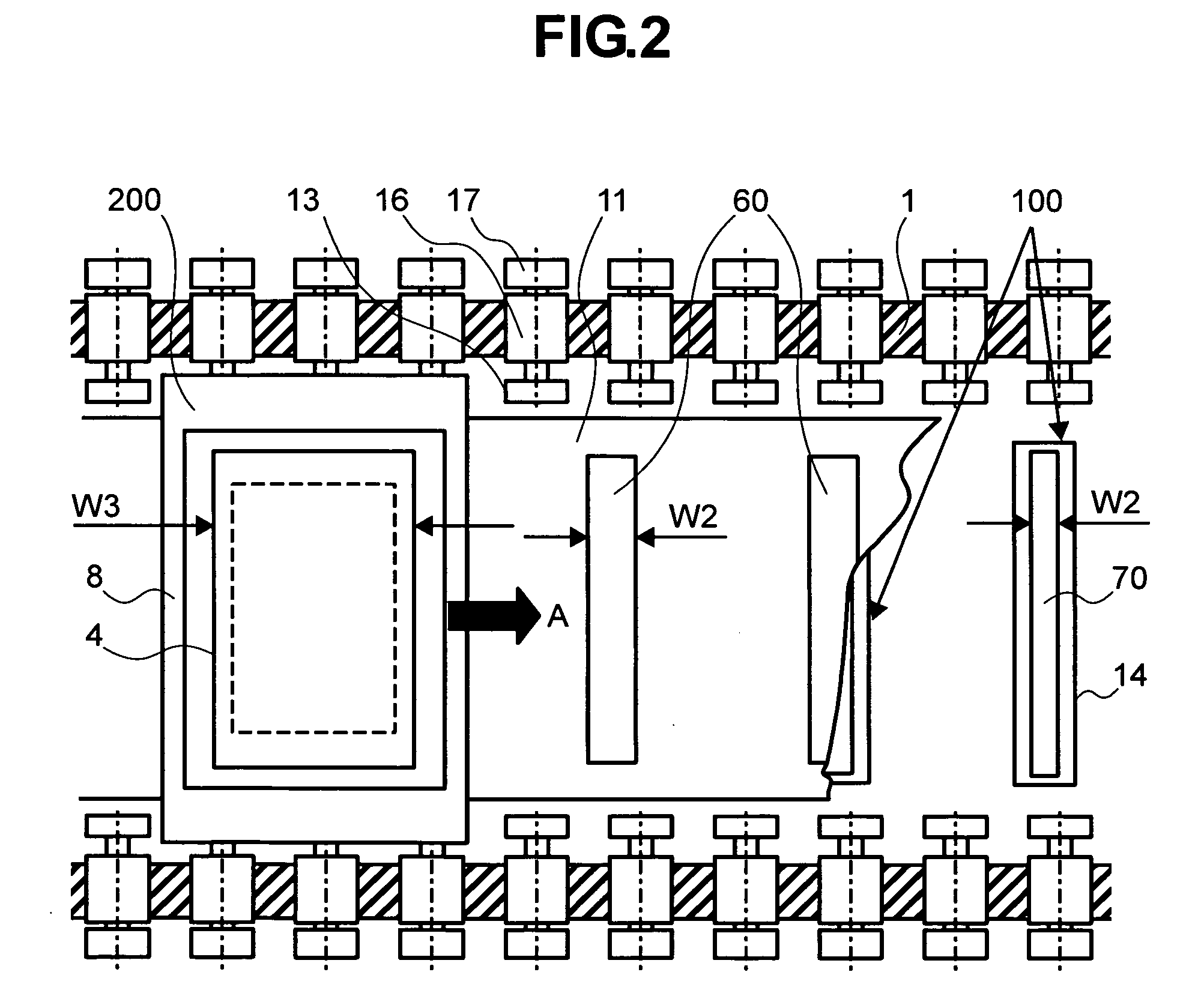
[0044]FIG. 1 is a cross-sectional view of a vapor deposition apparatus in a first embodiment of the invention. FIG. 2 is a plan view of the vapor deposition apparatus of FIG. 1, viewed from above. Any component similar to that in the previous example is provided with the same reference numeral. Inside of the vacuum chamber 1 being a vessel in a vacuum atmosphere, the evaporation source unit 100 is disposed. In the evaporation source unit 100, a material serving as an evaporation source is fixedly provided. The evaporation source unit 100 is formed with a vapor exhaust nozzle 70 from which jets of steam are directed. Above the evaporation source unit 100 in the vacuum chamber 1, the carrier set 200 is disposed to be moved by the transfer rollers 13 in the direction of an arrow A.

[0045]A cooling board 11 is provided to be a piece with the transferring carrier set 200 on the side closer to the evaporation source unit 100. The cooling board 11 is provided with, on the side of the evapor...

second embodiment

[0056]FIG. 3 is a cross-sectional view of a vapor deposition apparatus in a second embodiment of the invention, showing the cooling mechanism of a transfer roller. In FIG. 3, the transfer roller 13 and the carrier 8 are the same in basic configuration as those in the first embodiment, and the evaporation source unit 100 and the carrier set 200 are the same in configuration as those in the first embodiment. The cooling mechanism of the first embodiment shown in FIG. 1 is for cooling by heat radiation from the components, i.e., the carrier 8, the evaporation mask 5, and the substrate 4. Generally, cooling by heat conduction through contact is better in efficiency than cooling by radiation, and therefore, in the second embodiment, the transfer rollers 13 are each provided with the cooling capability.

[0057]In FIG. 3, a vacuum seal for the vacuum chamber 1 and the transfer roller 13 is implemented by a magnetic fluid seal unit 16. The magnetic fluid seal unit 16 is a combination of a mag...

third embodiment

[0060]FIG. 4 is a cross-sectional view of a vapor deposition apparatus in a third embodiment of the invention. In FIG. 4, the carrier set 200 is transferred from the paper surface side toward the front. FIG. 5 is a side view of the vapor deposition apparatus of FIG. 4 viewed from the substrate side. Note that, in the third embodiment, the mask frame 7 may be provided with the function of the carrier 8 so that the carrier 8 may not be necessarily provided. In the first embodiment, the carrier set 200 carrying therein the components, i.e., the carrier 8, the evaporation mask 5, and the substrate 4, is transferred in the horizontal direction. Alternatively, in the third embodiment, the carrier set 200 is disposed upright for transfer, and during transfer of such a carrier set 200, film formation is carried out. Also in the third embodiment, the evaporation source unit 100 is attached to the side wall surface of the vacuum chamber 1 to allow the steam 3 to reach all over the substrate 4...


PUM

PropertyMeasurementUnit
Lengthaaaaaaaaaa
Thicknessaaaaaaaaaa

Abstract

Provided is a method for moving, in a vacuum chamber carrying therein a fixedly-provided evaporation source, a substrate toward the evaporation source together with a mask closely attached to the substrate surface, and onto the surface substrate, evaporating a material vaporized in the evaporation source through an aperture formed to the mask. In this method of the invention, means for moving the substrate toward the evaporation source is provided with cooling means not to come in contact with but to be in proximity to a surface of the mask on the evaporation source side, and a cooling plate formed with an aperture proximal to the evaporation source is disposed. With such a configuration, the steam of the material coming from the evaporation source is directed to the mask and the substrate through the aperture of the cooling plate. As such, the material film evaporated on the substrate surface shows a satisfactory distribution of film thickness, and any possible misalignment from desired positions of evaporation can be accordingly suppressed.

Description

[0001]The present application claims priority from Japanese application JP2007-183242 filed on Jul. 12, 2007, the content of which is hereby incorporated by reference into this application.BACKGROUND OF THE INVENTION[0002]1. Field of the Invention[0003]The present invention relates to vapor deposition method and apparatus and, more specifically, to vapor deposition method and apparatus suitable for forming an organic material layer configuring an organic electroluminescence element.[0004]2. Description of the Related Art[0005]In an organic electroluminescence (hereinafter, organic EL) display device, organic EL elements to be driven by current are two-dimensionally arranged for image display. The organic EL elements are each generally configured by an insulator substrate formed thereon with a pair of electrodes. The substrate is made of glass, for example, and is exemplified by an active substrate formed thereon with a thin-film transistor or others for pixel driving. On one of the ...

Claims


Application Information

Patent Timeline
IPC IPC(8): B05D5/12C23C16/04
CPCC23C14/042H01L51/56H01L51/001C23C14/56C23C14/541H10K71/164H10K71/00
Inventor MATSUURA, HIROYASU
Owner HITACHI DISPLAYS
Why Eureka
Try Eureka