Method and apparatus of indirect-evaporation cooling

a technology of indirect evaporation and cooling, which is applied in the direction of domestic cooling apparatus, lighting and heating apparatus, heating types, etc., can solve the problems of product fluids that cannot be cooled, inability to cool materials other than air or gas, and certain drawbacks and limitations, so as to achieve low energy consumption, low energy cost, and low energy cost

Inactive Publication Date: 2002-12-24
F F SEELEY NOMINEES
View PDF20 Cites 140 Cited by
  • Summary
  • Abstract
  • Description
  • Claims
  • Application Information

AI Technical Summary

Benefits of technology

In the present method of indirect-evaporation cooling this heat exchange apparatus, according to the invention, it is possible to cool air, gas, refrigerant, steam, liquid, and any material, which can be transported along channels. The different variations of this apparatus are useful because they permit cooling gaseous, liquid and dispersed materials without high-energy cost for cooling. ...

Problems solved by technology

However they have certain drawbacks and limitations due to their designs.
The essential disadvantages of the described method and the apparatus for effecting same are: 1) the Product Fluid can not be cooled even in an ideal case lower than the temperature of the dew point of outside air; 2) the impossibility of cooling materials other than air or gas and; 3) difficult to realize cooling process for use in vehicles.
The essential disadvantages of the described method and the apparatus for effecting same are: 1) the water being cooled can not be cooled even in an ideal case lower then the dew point temperature of outside air; 2) The ability to cool only water; 3) This process does not use an induced draft exhaust system and; 4...

Method used


Image

  • Method and apparatus of indirect-evaporation cooling
  • Method and apparatus of indirect-evaporation cooling
  • Method and apparatus of indirect-evaporation cooling

Examples


Embodiment Construction

For purposes of illustrating the advantages of the apparatus and method disclosed herein, the applicants take the results using the apparatus disclosed in Russian patent No. 2046257 (Maisotsenko) [copied in U.S. Pat. No. 5,187,946]. We compare the results using the apparatus shown in FIG. 3 in Table #1.

The materials as used in the test of FIG. 3 are a wicking material on the wet surfaces made of cellulose blended fiber sold by Ahlstrom Paper Group, Grade 1278 (0.2969 mm thickness), backed, for the dry side of the membrane, with 5 mil Mylar callendered with an adhesive (appropriate for the material).

This material is the best readily available product, though other materials may be used, such as an absorbent material, such as polypropylene with a; polyethylene coating which was available from Ahlstrom as Grade 4002. Another combination, using polyethylene coating on the Grade 1278, would have additional advantages.

The advantage of Grade 1278 is that it is specifically a wicking materi...


PUM


Abstract

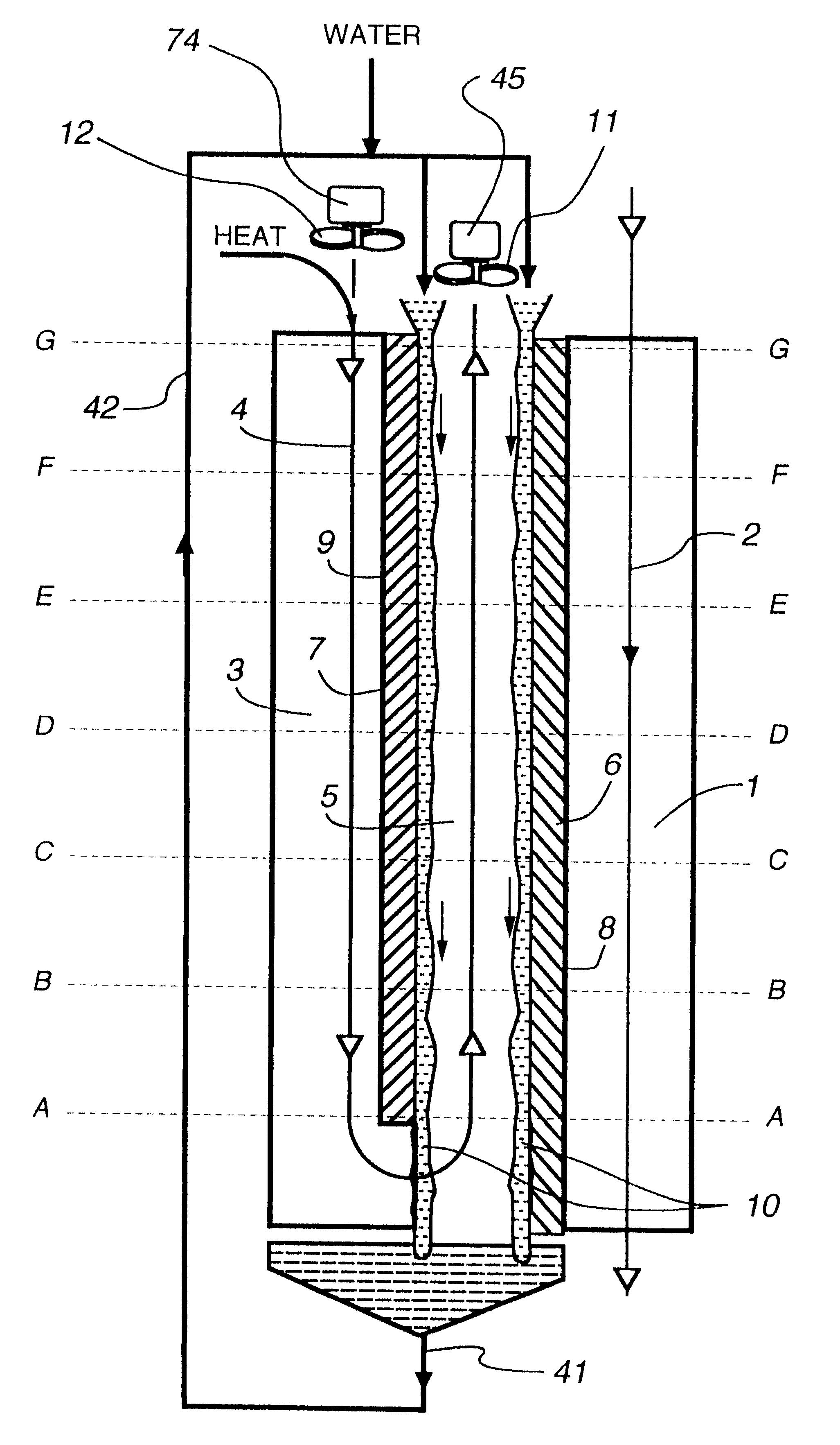
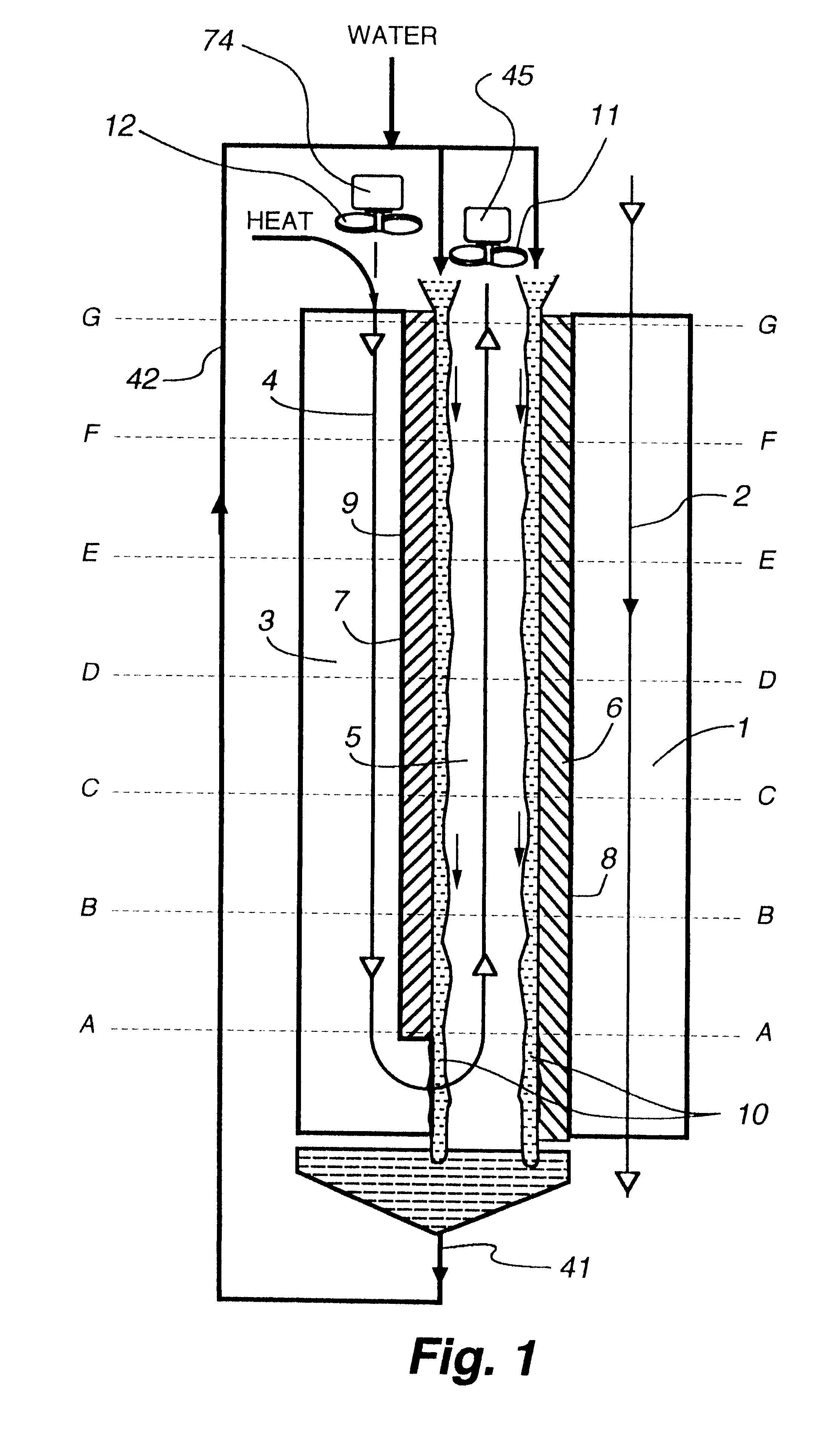
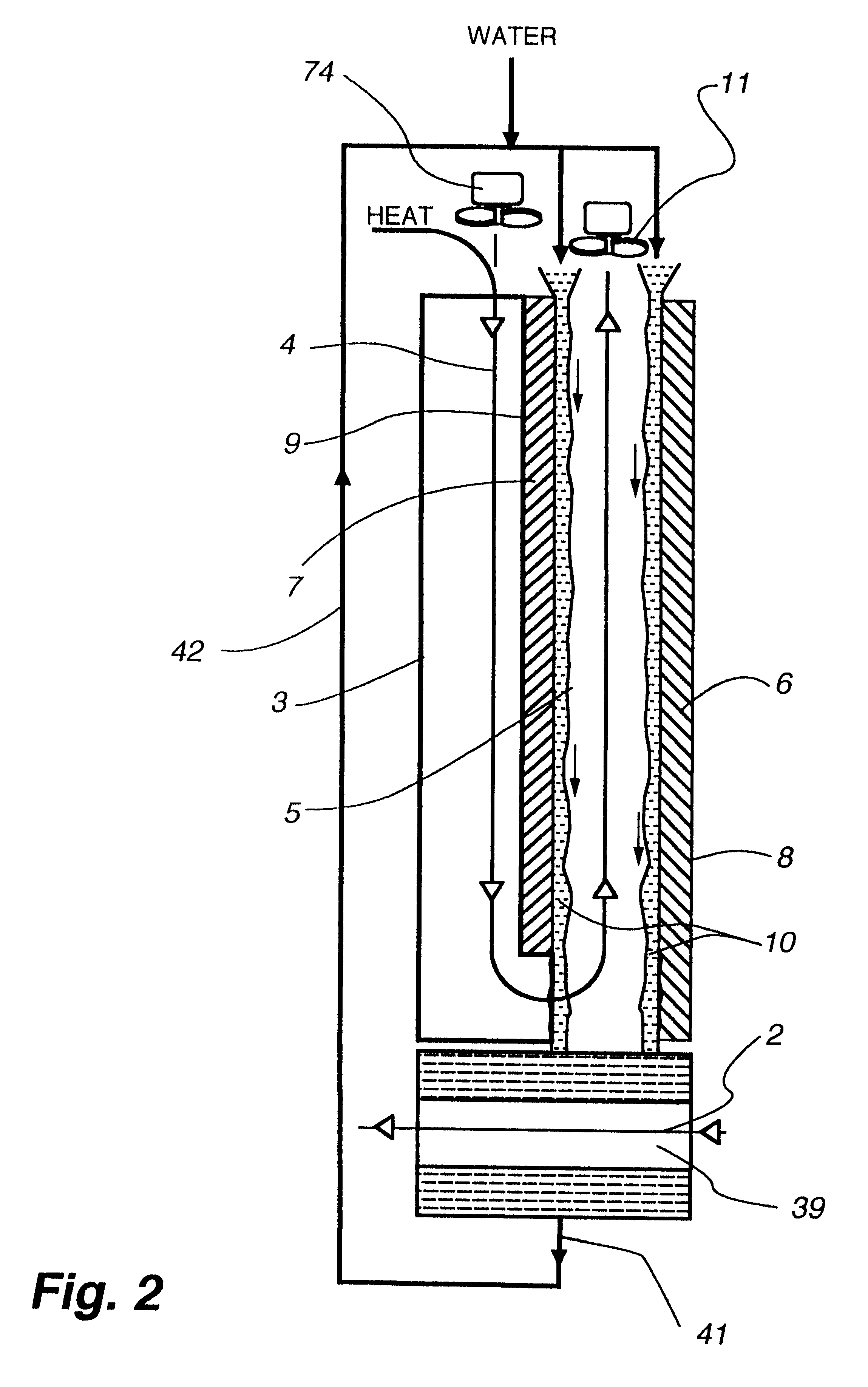
The within invention improves on the indirect evaporative cooling method and apparatus by making use of a working fluid that is pre-cooled with and without desiccants before it is passed through a Wet Channel where evaporative fluid is on the walls to take heat and store it in the working fluid as increased latent heat. The heat transfer across the membrane between the Dry Channel and the Wet Channel may have dry, solid desiccant or liquid desiccant and may have perforations, pores or capillary pathways. The evaporative fluid may be water, fuel, or any substance that has the capacity to take heat as latent heat. The Wet Channel or excess cooled fluid is in heat transfer contact with a Product Channel where Product Fluid is cooled without adding any humidity. An alternative embodiment for heat transfer between adjacent channels is with heat pipes.

Description

1. The present invention relates to methods of indirect-evaporation cooling of fluids and to heat exchange apparatus for affecting these methods.2. The invention can be used for air conditioning, as well as cooling liquids and gases in different technological processes. It can be used to cool materials that can be conveyed along the heat transfer surfaces of the apparatus by methods other than fluidization.The use of Evaporative methods to cool gases is well-known. The use of adjacent channels or heat transfer services to allow an evaporation in one channel to provide cooling for material in the second channel is also well-known, see. Niehart 2,174,060.The methods and apparatus to cool air through evaporation have proved useful over many years. However they have certain drawbacks and limitations due to their designs.There is known in the art a method of indirect-evaporation cooling of air, comprising cooling the flow of outside air over a heat exchange apparatus (USSR Patent No. 979...

Claims


Application Information

Patent Timeline
IPC IPC(8): F28D5/02F28D5/00F24F1/0059
CPCF28D5/02F24F2001/0092Y02B30/545F24F1/0007F24F5/0035Y02B30/54F24F1/0059
Inventor MAISOTSENKO, VALERIYGILLAN, LELAND E.HEATON, TIMOTHY L.GILLAN, ALAN D.
Owner F F SEELEY NOMINEES
Why Eureka
Try Eureka