Pattern coil type vertical vibrator

Inactive Publication Date: 2006-01-05
SAMSUNG ELECTRO MECHANICS CO LTD
View PDF7 Cites 23 Cited by
  • Summary
  • Abstract
  • Description
  • Claims
  • Application Information

AI Technical Summary

Benefits of technology

[0028] Therefore, the present invention has been made in view of the above problems, and it is an object of the present invention to provide a pattern coil type vertical vibrator, whic

Problems solved by technology

However, when the above-structured vibrating motor 1 is driven, the brushes 25 pass through a space between segments of the commutator 15, thus causing mechanical friction and electrical sparks between the brushes 25 and the segments of the commutator 15 and abrasion of the brushes 25 and the commutator 15, thereby producing foreign substances, such as black powder and shortening the lifespan of the motor.
The actuator 2 requires a large number of components and has a complicate

Method used


Image

  • Pattern coil type vertical vibrator
  • Pattern coil type vertical vibrator
  • Pattern coil type vertical vibrator

Examples


Embodiment Construction

[0055] Now, preferred embodiments of the present invention will be described in detail with reference to the annexed drawings.

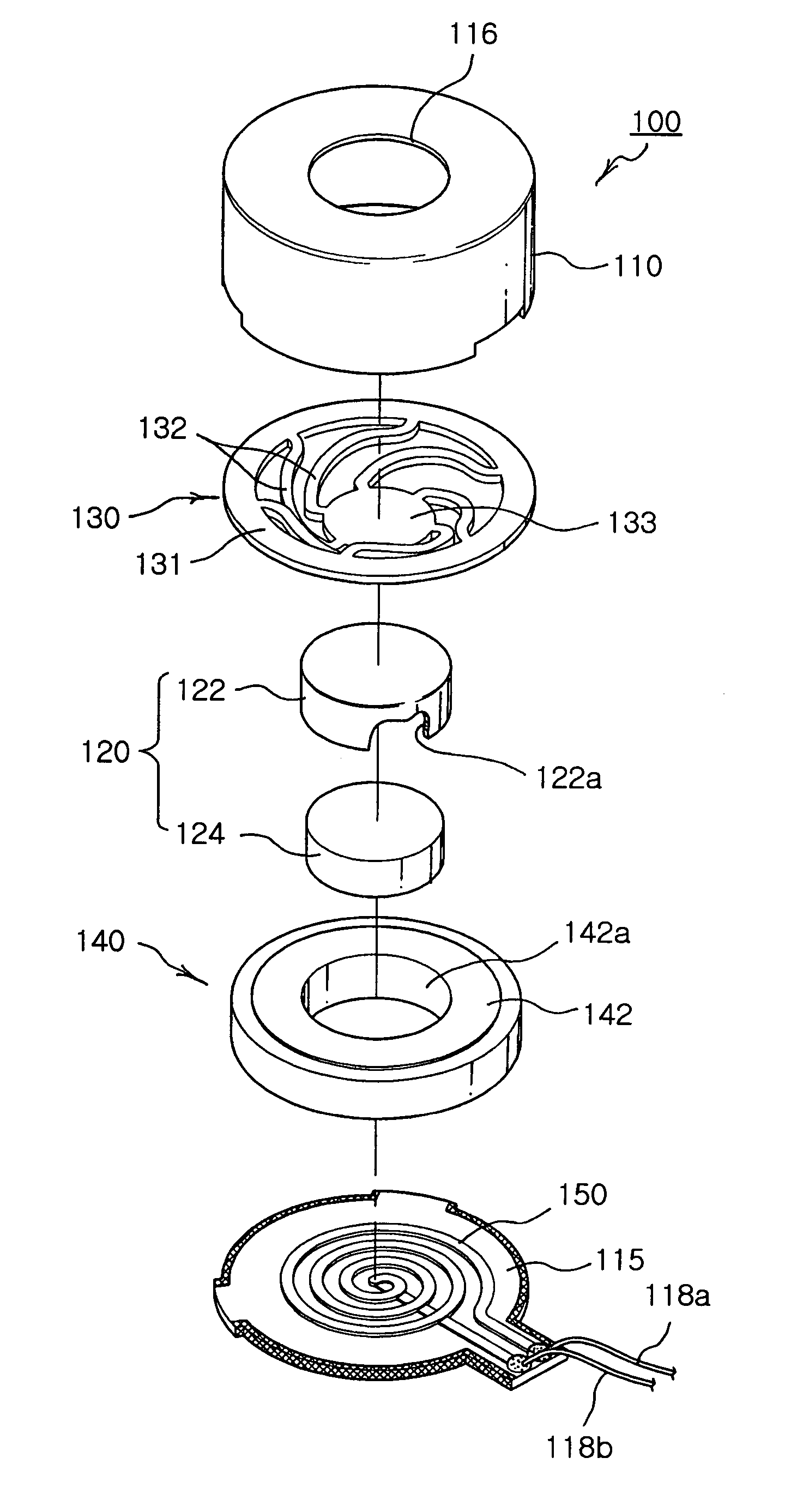
[0056]FIGS. 4a and 4b illustrate a pattern coil type vertical vibrator in accordance with a first embodiment of the present invention, and FIG. 5 is an exploded perspective view of the pattern coil type vertical vibrator in accordance with the first embodiment of the present invention.

[0057] As shown in FIGS. 4a and 4b and FIG. 5, the vertical vibrator in accordance with the first embodiment of the present invention comprises a housing 10, a magnetic circuit unit 120, spring members 130, a vibrating unit 140, a pattern coil 150 formed on a base for generating force interlinked with a magnetic field, thereby reducing the number of components and the number of steps of an assembling process, having a thin thickness, and maximizing a vertical vibrating width in a limited space.

[0058] That is, the housing 110 having a hollow cylindrical structure serves as a r...


PUM


Abstract

Disclosed is a pattern coil type vertical vibrator including: a housing; a magnetic circuit unit placed in the internal space of the housing, and including a magnet perpendicularly placed and a yoke for fixedly receiving the magnet therein; spring members provided with upper ends fixed to the housing and lower ends fixed to the magnetic circuit unit for vertically and elastically supporting the magnetic circuit unit; a vibrating unit, including a weight assembled with the yoke of the magnetic circuit unit, vertically vibrated together with the magnetic circuit unit through the spring members; and a pattern coil, printed on an upper surface of a base for closing a lower surface of the housing, to which power is supplied, so that the pattern coil is interlinked with a magnetic field generated from the magnet and generates force just upwardly when the power is supplied to the pattern coil.

Description

BACKGROUND OF THE INVENTION [0001] 1. Field of the Invention [0002] The present invention relates to a vertical vibrator, and more particularly to a pattern coil type vertical vibrator, in which the pattern of a coil serving as a route for current are printed on a base, thereby reducing the number of required components and the number of steps of a manufacturing process and facilitating the thin profile of products. [0003] 2. Description of the Related Art [0004] Generally, sound and vibration are used to inform users of an incoming call. A small-sized vibrating motor is driven to generate vibration, and driving force of the vibrating motor is transmitted to a housing of a device, thereby vibrating the whole portions of the device. [0005] A vibrating motor, which is one incoming call notification means applied to a communication device, such as a cellular phone, converts electrical energy to mechanical energy using the principle of electromagnetic force, and is installed in a cellul...

Claims


Application Information

Patent Timeline
IPC IPC(8): H02K7/06
CPCH02K33/16B06B1/045B06B1/04
Inventor WON, SUNG HONGHONG, SEONG PYOCHOI, JOONKIM, JU HO
Owner SAMSUNG ELECTRO MECHANICS CO LTD
Why Eureka
Try Eureka