
Directional bridge coupler

a technology of directional bridges and couplers, applied in the direction of coupling devices, multiple-port networks, electrical devices, etc., can solve the problems of cumbersome switching arrangement, poor performance of proximity couplers at high operating frequencies, and poor performance of high operating frequencies

Inactive Publication Date: 2006-01-05
AGILENT TECH INC
View PDF3 Cites 14 Cited by
  • Summary
  • Abstract
  • Description
  • Claims
  • Application Information

AI Technical Summary

Benefits of technology

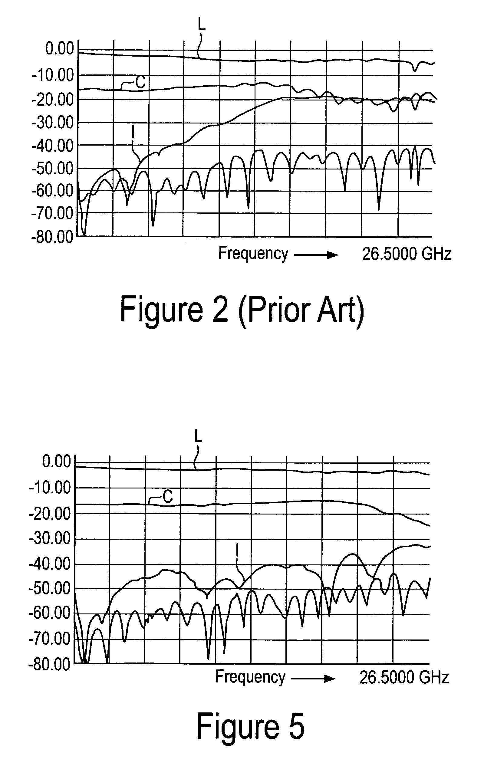
[0005] A directional bridge coupler according to embodiments of the present invention provides a low frequency operating limit comparable to that of a directional bridge, and a high frequency operating limit comparable to that of a proximity coupler. The directional bridge coupler has an operating frequency range that is wide enough to accommodate a broadband network measurement system.

Problems solved by technology

Thus, the directional bridge, which has excellent performance at low operating frequencies, has poor performance at high operating frequencies.
While proximity couplers generally have poor performance at low frequencies, proximity couplers can be designed to have high-frequency operating limits that exceed twenty gigahertz.
However, this switched arrangement is cumbersome since it requires the two couplers, the switch, and a control signal to set the position of the switch.
The switch also has the disadvantage of introducing power losses at the test ports of the network measurement system, which can reduce the measurement sensitivity of the network measurement system within which the switched coupler arrangement is included.

Method used


Image

  • Directional bridge coupler
  • Directional bridge coupler
  • Directional bridge coupler

Examples


Embodiment Construction

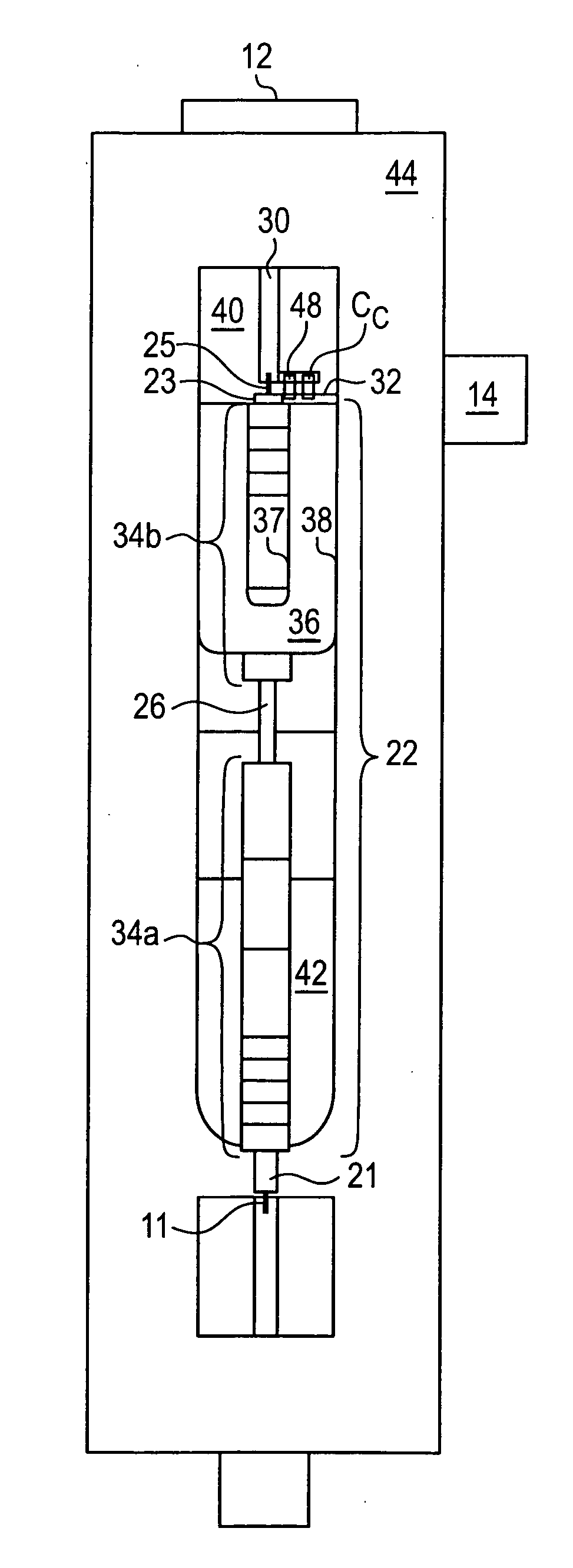
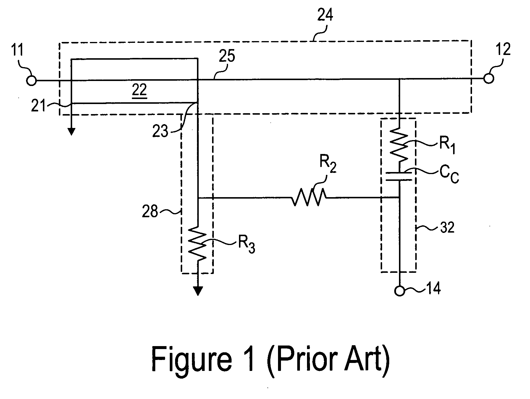
[0011] A directional bridge coupler 20 according to the embodiments of the present invention is shown in FIG. 3. The directional bridge coupler 20 is based on the schematic diagram of a directional bridge 10 shown in FIG. 1. One commercial implementation of a directional bridge 10 is included in the model N338xA series Performance Vector Network Analyzer, from AGILENT TECHNOLOGIES, INC., Palo Alto, Calif., USA. This prior art implementation of the directional bridge has an associated performance indicated in the response plot of FIG. 2. In this response plot, isolation I between designated ports in this implementation of the directional bridge 10 steadily degrades at frequencies above approximately 5 GHz. Directivity D, an important performance parameter of the directional bridge 10 that depends on the isolation I, insertion loss L, and coupling C, correspondingly degrades at frequencies above 5 GHz.

[0012] This degraded performance at higher operating frequencies renders this prior...


PUM


Abstract

A directional bridge coupler includes a coaxial balun having a coaxial cable with a plurality of ferrite beads disposed about an outer conductor of the coaxial cable, and a circuit substrate accommodating a directional bridge coupled to an output of the coaxial bridge. A conductive package having an internal cavity houses the circuit substrate and the coaxial balun. A polyiron saddle straddles a portion of the coaxial balun within the internal cavity of the conductive package.

Description

BACKGROUND OF THE INVENTION [0001] Couplers play an important role in network measurement systems. In addition to providing connections between a network measurement system and a device under test (DUT), couplers provide the important function of separating incident and reflected waves for network measurements. A measure of this separation between incident and reflected waves, referred to as directivity, influences the measurement accuracy of the network measurement system. Higher directivity generally increases measurement accuracy. Directivity is an especially important performance measure of a coupler when measuring DUTs that have impedance-matched ports and attenuation losses that result in reflected waves that have low magnitudes. [0002] One known type of coupler, shown in the schematic diagram of FIG. 1, is a directional bridge. The directional bridge is commonly used in network measurement systems, such as scalar and vector network analyzers. While the directional bridge prov...

Claims


Application Information

Patent Timeline
Patent Type & Authority Applications(United States)
IPC IPC(8): H01P5/18
CPCH01P5/10H01P5/02
Inventor FOJAS, URIEL C.
Owner AGILENT TECH INC
Learn More