Map display system and digital camera

a map display system and digital camera technology, applied in the field of map display systems and digital cameras, can solve the problems of inconvenient capture of plural subjects and inability to identify each subject exactly, and achieve the effect of convenient differentiation

a map display system and digital camera technology, applied in the field of map display systems and digital cameras, can solve the problems of inconvenient capture of plural subjects and inability to identify each subject exactly, and achieve the effect of convenient differentiation

US20060001757A1Active Publication Date: 2006-01-05FUJIFILM CORP

Image

  • Map display system and digital camera
  • Map display system and digital camera
  • Map display system and digital camera

Examples


Embodiment Construction

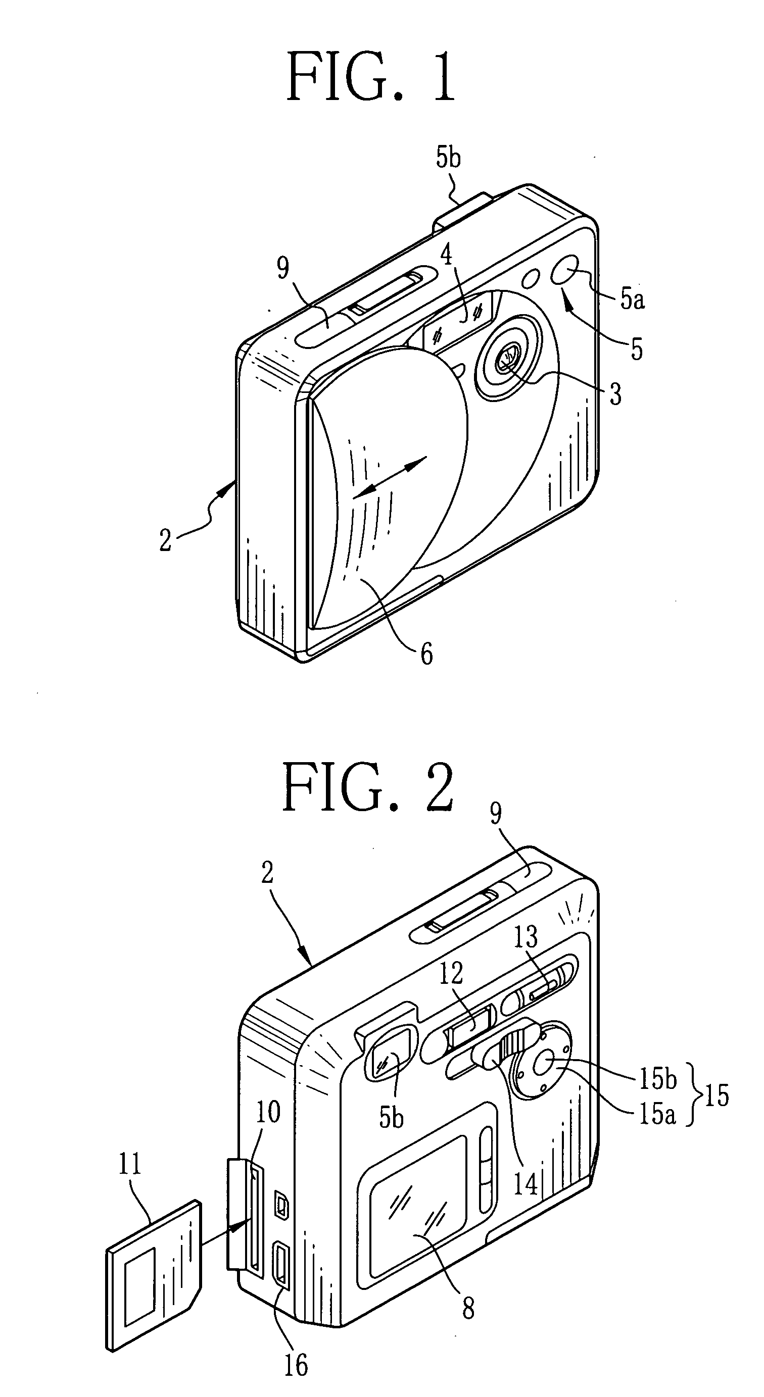
[0033] In FIG. 1, a taking lens 3, a flash emitter 4, a front viewfinder window 5a of an optical viewfinder 5 and a lens barrier 6 are disposed on the front of a digital camera 2. The lens barrier 6 is slidable between a close position and an open position, in which the lens barrier 6 covers and uncovers the taking lens 3 and the flash emitter 4. In the open position, a power of the digital camera 2 is turned on.

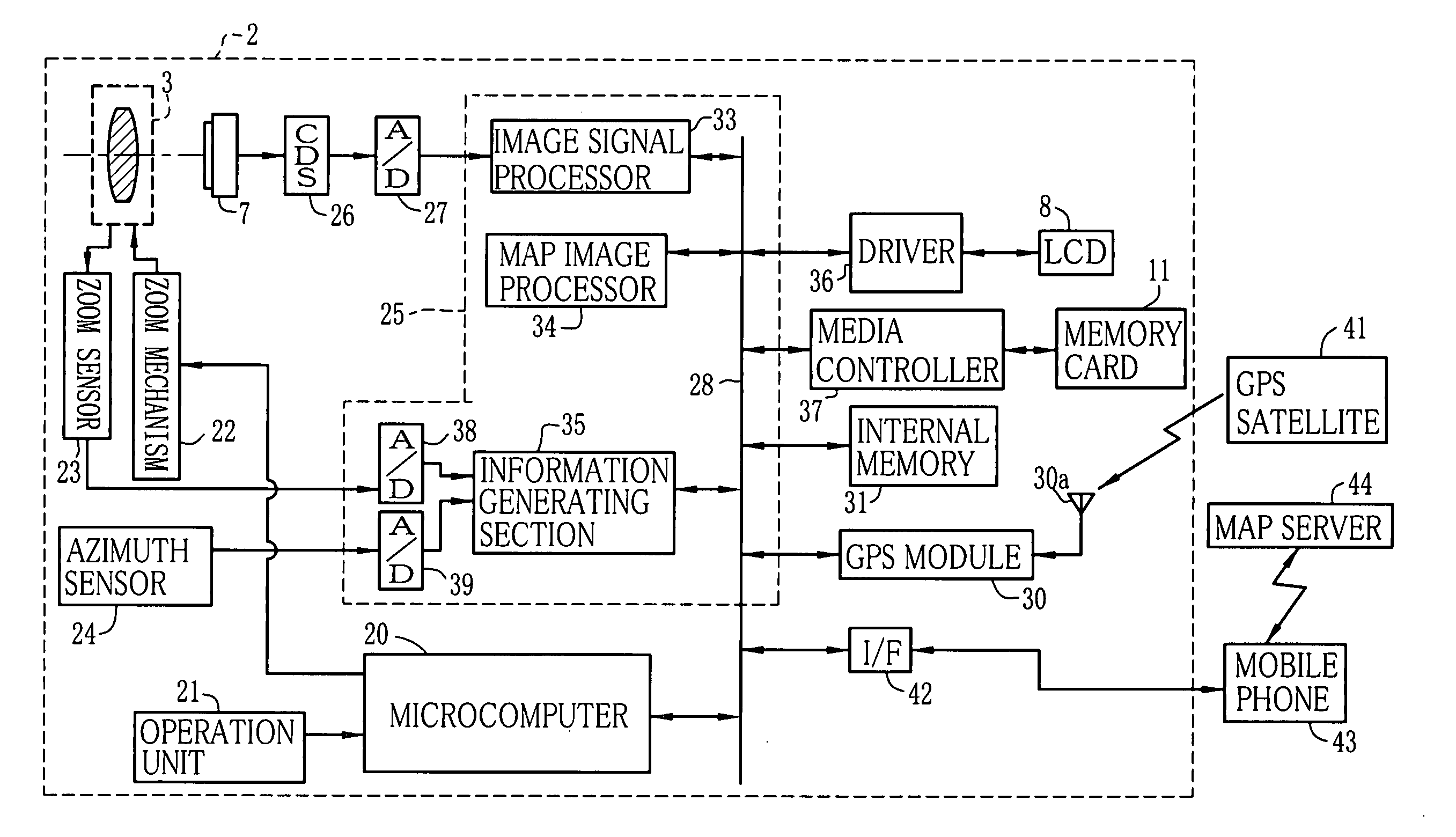
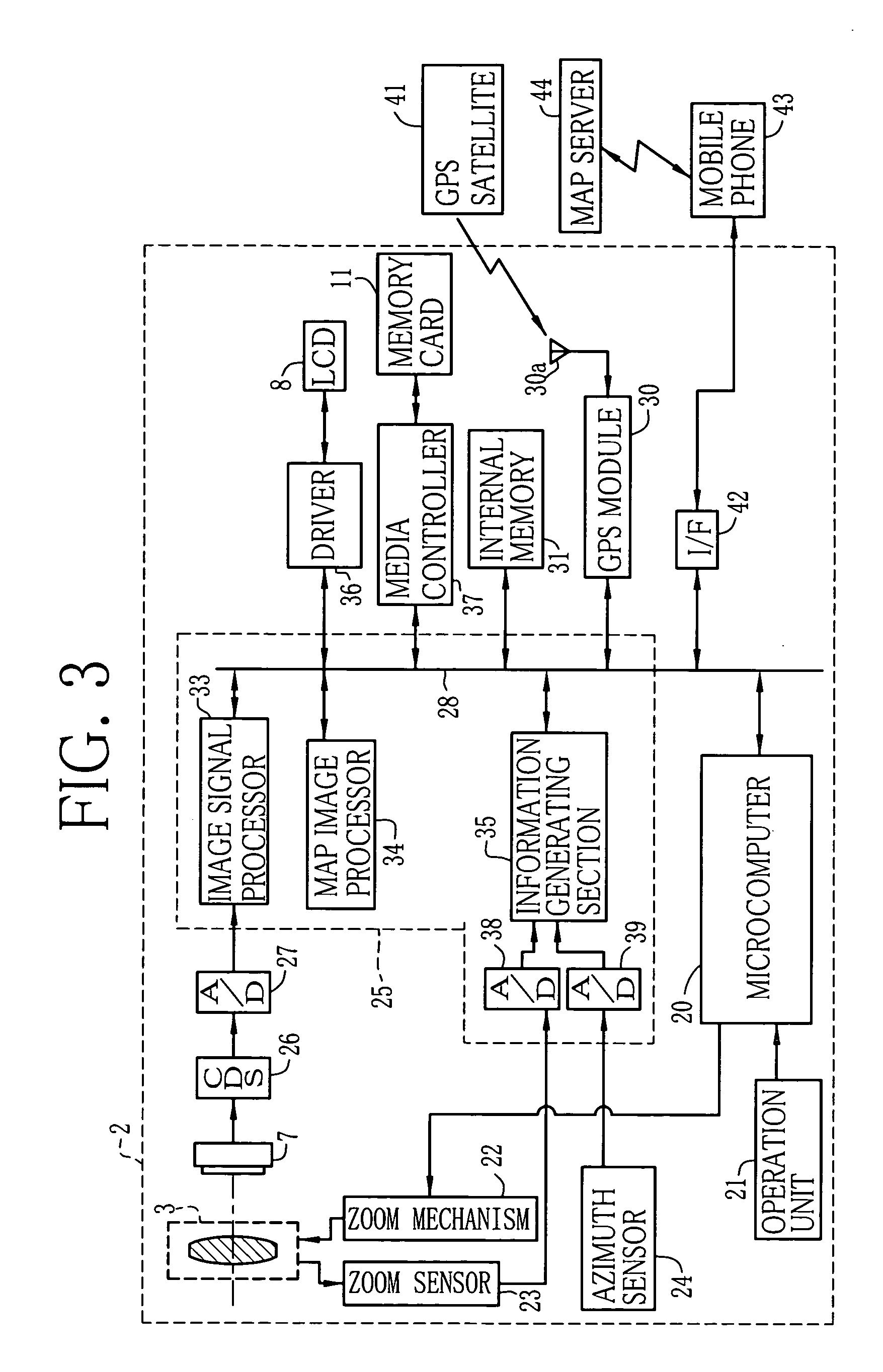
[0034] At the rear of the taking lens 3, a CCD image sensor 7 is disposed (see FIG. 3). An image captured by the CCD image sensor 7 during a framing is displayed as a so-called through image in an LCD (Liquid Crystal Display) 8 which is disposed at the back of the digital camera 2. The LCD 8 is used for reproducing the captured still image besides displaying the through image. In FIG. 2, a rear viewfinder window 5b of the optical viewfinder 5 is disposed at the back of the digital camera 2. Through the rear viewfinder window 5b, a user can observe the through images display...


PUM


Abstract

A digital camera receives position information from GPS satellites for detecting camera position when capturing an image. Additional information, which is composed of the camera position, camera azimuth and focal distance of the taking lens, is added to image data of the captured image as tag and recorded in an image file. When the captured image is reproduced, the map image generated according to the additional information is displayed below the captured image, covering an area from the image capture point toward the subject in the captured image. Field view lines and map symbols indicating the subjects are displayed in the map image. Further, the map image includes the extension line which passes the map symbol and is extended to the subject in the captured image for showing the correspondence between the map symbol and the subject.

Description

BACKGROUND OF THE INVENTION [0001] 1. Field of the Invention [0002] The present invention relates to a map display system and a digital camera for displaying a map in association with a captured still image. [0003] 2. Background Arts [0004] Digital camera converts a subject image captured by an image sensor such as a CCD into an image signal, and records the image signal in a recording medium such as an internal memory, a memory card and the like. Japanese Patent Laid-Open Publication Nos. 9-98323, 2001-169164 and 2001-216309 disclose digital cameras and the like which detect a camera position and a camera azimuth and record the detected results and names of the subjects in association with the image signal. [0005] Each of the digital cameras disclosed in the above references includes a GPS processing unit for receiving signals from a GPS satellite to detect the camera position, an azimuth sensor for detecting the camera azimuth and a distance sensor for detecting a camera-to-subjec...

Claims


Application Information

Patent Timeline
05 Jan 2006
Publication
US20060001757A1
IPC
H04N5/222
CPC
G01C21/20; H04N1/32128; H04N5/232; H04N2201/3214; H04N2201/3277; H04N2201/3252; H04N2201/3253; H04N2201/3273
Inventors
SAWACHI, YOUICHI