
Hard disk drive

a hard disk drive and hard disk technology, applied in the field of hard disk drives, can solve the problems of negative affecting recording and reproducing operations of hdd, position error signals (pess), etc., and achieve the effect of preventing turbulen

Inactive Publication Date: 2006-01-05
SAMSUNG ELECTRONICS CO LTD
View PDF16 Cites 17 Cited by
  • Summary
  • Abstract
  • Description
  • Claims
  • Application Information

AI Technical Summary

Benefits of technology

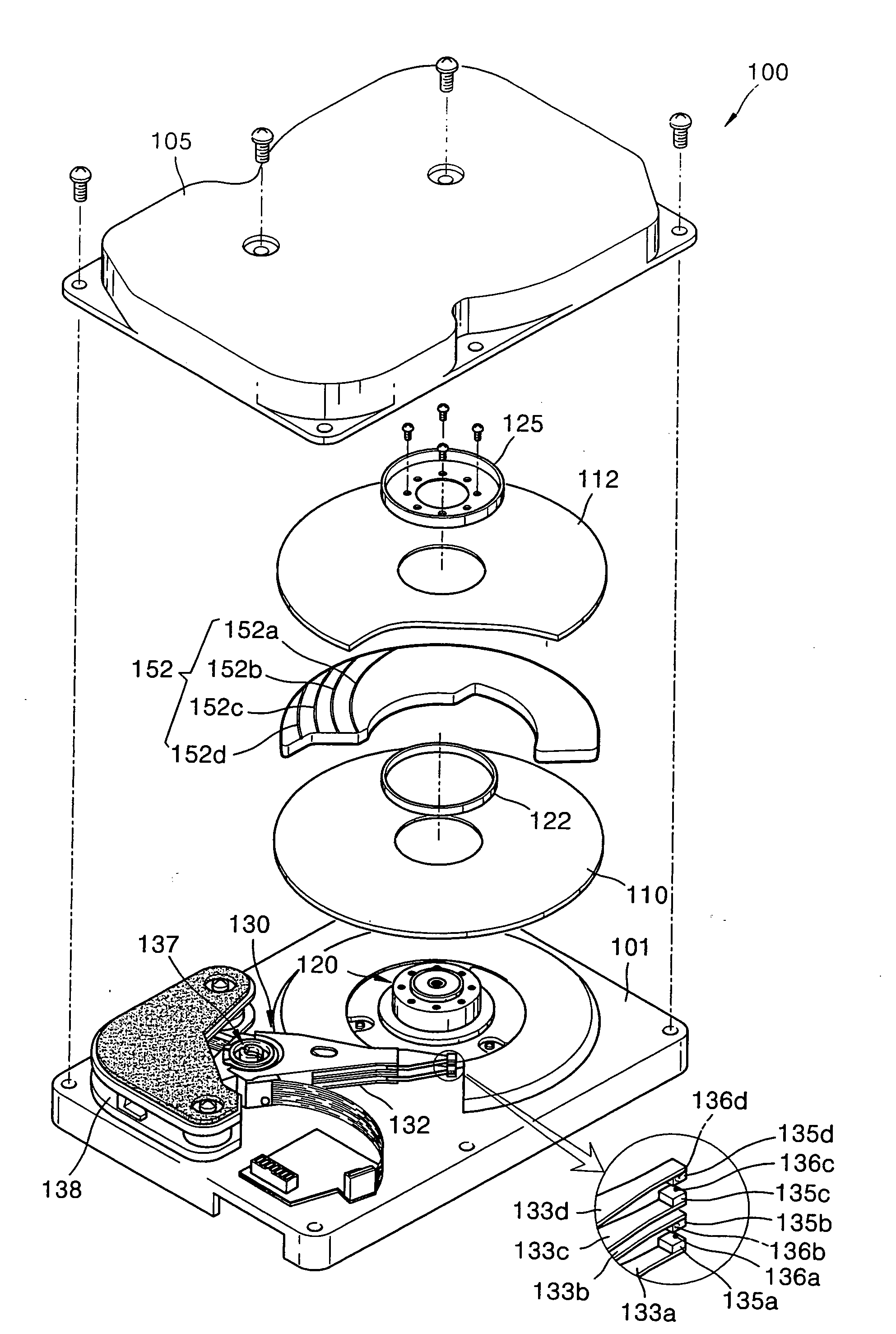
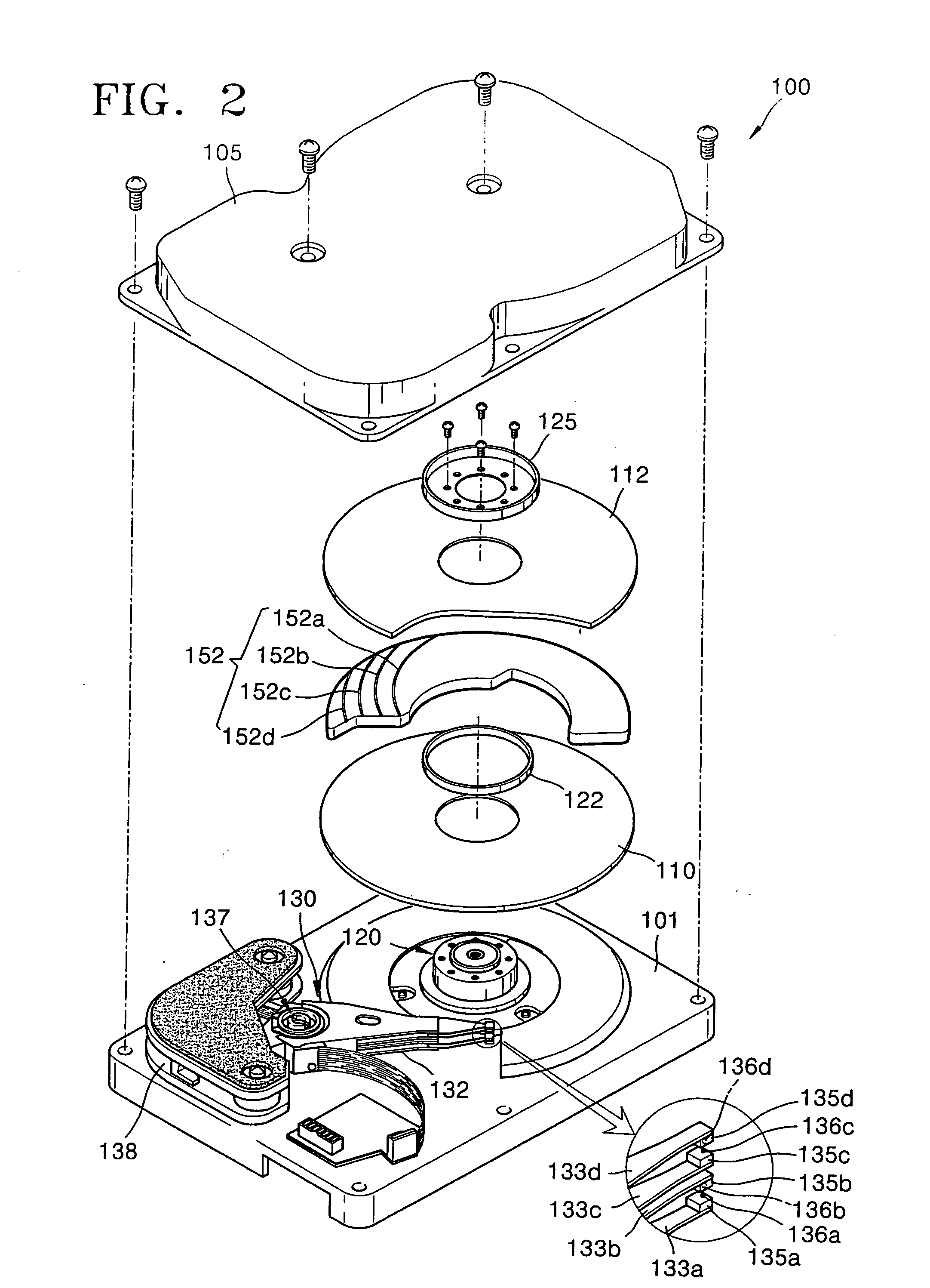
[0013] The present invention provides a hard disk drive (HDD), which prevents turbulence by disposing a damper, on which grooves are formed, between stacked disks.
[0018] The damper may be mounted on the base member so as to not contact the two disks or disturb the rotation of the actuator. The damper may have a “C” shape thereby facing only a portion of the surface area of the respective at least one of the two disks. Accordingly, the groove can suppress turbulence generated by the rotation of at least one of the two disks. The groove may also be one of a plurality of radial grooves suppressing turbulence.
[0020] To achieve the above and / or other aspects and advantages, embodiments of the present invention set forth a disk drive turbulence suppression method, including rotating a plurality of disks rotatably stacked on a base member and spaced apart from one another, and dampening turbulence between at least two of the plurality of stacked disks, comprising channeling air through at least one groove formed on at least one surface of at least one damper respectively facing at least one of the two disks.

Problems solved by technology

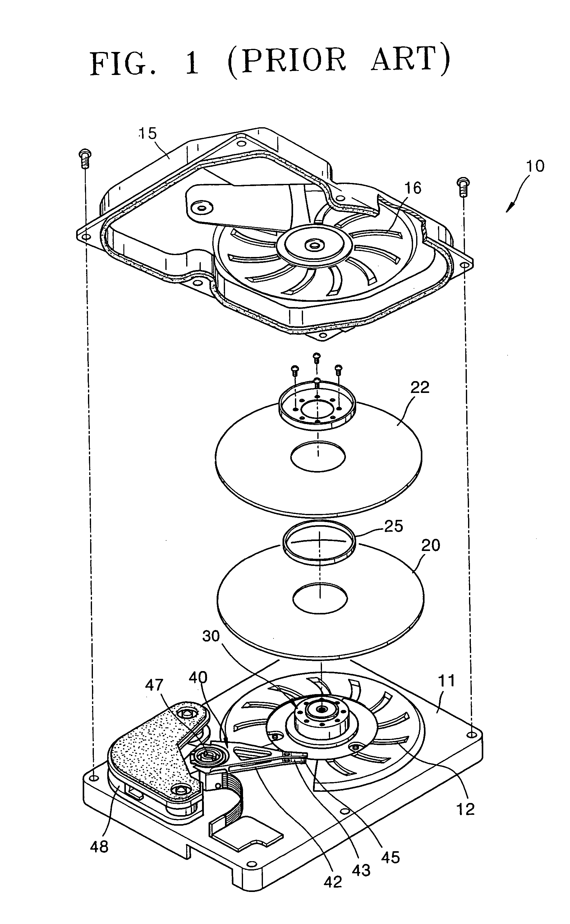
Such vibrations cause position error signals (PESs) and negatively affect recording and reproducing operations of the HDD 10.

Method used


Image

  • Hard disk drive
  • Hard disk drive
  • Hard disk drive

Examples


Embodiment Construction

[0029] Reference will now be made in detail to the embodiments of the present invention, examples of which are illustrated in the accompanying drawings, wherein like reference numerals refer to the like elements throughout. The embodiments are described below to explain the present invention by referring to the figures.

[0030]FIG. 2 illustrates an exploded perspective view of a hard disk drive (HDD), according to an embodiment of the present invention. Similarly, FIG. 3 illustrates a top plan view of a damper for the HDD shown in FIG. 2, and FIG. 4 illustrates a sectional view of the HDD shown in FIG. 2.

[0031] Referring to FIGS. 2 and 4, a HDD 100 includes a housing, formed by attaching a cover member 105 to a base member 101, with a predetermined inner space therein. First and second disks 110 and 112, a spindle motor 120, an actuator 130, and a damper 150 reside within the housing.

[0032] The housing includes the base member 101 that supports the spindle motor 120 and the actuato...


PUM


Abstract

A hard disk drive (HDD) and method, with the HDD including a housing, having a base member and a cover member attached to each other, a plurality of disks, rotatably stacked on the base member and spaced apart from one another, an actuator installed on the base member to rotate around a pivot and fixedly supporting, on its leading end, a slider on which a magnetic head for recording or reproducing data to or from the disks is mounted, and a damper, disposed between the stacked disks, wherein a groove is formed on surfaces of the damper facing the disks.

Description

CROSS-REFERENCE TO RELATED APPLICATIONS [0001] This application claims the priority benefit of Korean Patent Application No. 2004-51976, filed on Jul. 5, 2004, in the Korean Intellectual Property Office, the disclosure of which is incorporated herein in its entirety by reference. BACKGROUND OF THE INVENTION [0002] 1. Field of the Invention [0003] The present invention relates to a hard disk drive (HDD), and more particularly, to an HDD and method for suppressing turbulence during the rotation of a HDD disk. [0004] 2. Description of the Related Art [0005] Hard disk drives (HDDs), which are auxiliary memory devices for computers, reproduce information stored in a magnetic disk or record new information on the magnetic disk by way of a magnetic head. There have been demands for HDDs to have higher capacity and operate at higher speeds with lower vibrations. To meet these demands, extensive research and development efforts have been made. [0006]FIG. 1 is an exploded perspective view of ...

Claims


Application Information

Patent Timeline
IPC IPC(8): G11B33/14
CPCG11B33/148G11B25/043G11B33/08
Inventor LIM, HONG-TAEK
Owner SAMSUNG ELECTRONICS CO LTD
Learn More