Methods and devices for scheduling the transmission of packets in configurable access wireless networks that provide Quality-of-Service guarantees

a wireless network and configurable access technology, applied in the field of methods and devices for scheduling the transmission of packets, can solve the problems of difficult to reduce packet re-transmission, inability to relay packets through the station, and inability to easily achieve packet transmission, etc., to achieve the effect of conserving energy

Inactive Publication Date: 2006-01-05
LUCENT TECH INC
View PDF6 Cites 28 Cited by
  • Summary
  • Abstract
  • Description
  • Claims
  • Application Information

AI Technical Summary

Benefits of technology

[0007] Slots are assigned to each station by making use of a scheduling graph. Within each graph, a so-called Hamiltonian Cycle is identified. The cycle is used to identify those slots which should be assigned to each station (i.e., be a part of its schedule) to avoid collisions, and thus conserve energy, while at the same time providing both bandwidth and delay QoS guarantees.

Problems solved by technology

If one of the stations along the path the packets must travel fails because it runs out of available energy (i.e., its batteries run down), the packets cannot be relayed through that station.
However, this cannot be easily achieved when packets are transmitted in bursts, as opposed to in a continuous stream.
Even in wireless networks that transmit packets in a continuous stream (e.g., Time Division, Multiple Access networks), it has been difficult to reduce packet re-transmissions and still meet Quality of Service (QoS) guarantees.
While these techniques may reduce collisions and re-transmissions, they do so by sacrificing QoS guarantees related to delay.
For example, one scheduling technique known as an edge coloring technique, has been able to reduce re-transmissions and provide QoS guarantees related to bandwidth, but has been unable to provide QoS guarantees related to delay.

Method used


Image

  • Methods and devices for scheduling the transmission of packets in configurable access wireless networks that provide Quality-of-Service guarantees
  • Methods and devices for scheduling the transmission of packets in configurable access wireless networks that provide Quality-of-Service guarantees
  • Methods and devices for scheduling the transmission of packets in configurable access wireless networks that provide Quality-of-Service guarantees

Examples


Embodiment Construction

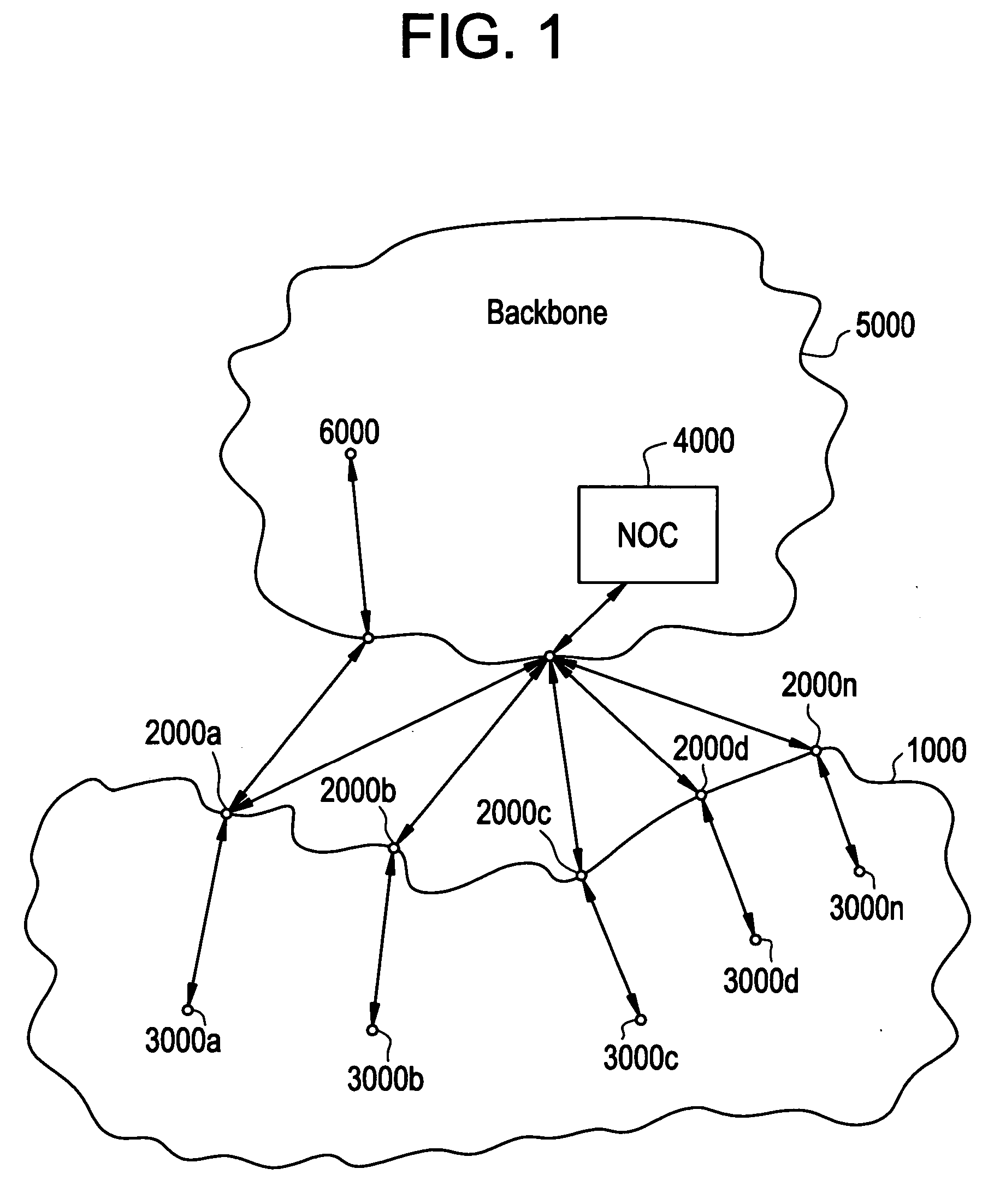
[0014] Referring now to FIG. 1, there is shown a simplified illustration of a TDMA-based CAN 1000 according to one embodiment of the present invention. As shown, CAN 1000 includes one or more access point stations (APs) 2000a,2000b, . . . 2000n and non-AP stations (“stations”) 3000a,3000b, . . . 3000n (where “n” is the last AP or station). In one embodiment of the present invention, CAN 1000 is connected to, and receives at least configuration and activation messages from an external controller 4000 referred to as a network operation center (“NOC”) or just controller. In an embodiment of the present invention, the NOC 4000 is operable to determine: the topology of CAN 1000; routing paths associated with each station; and packet transmission schedules associated with each station. Based on the routes and transmission schedules determined at a given point in time, the NOC 4000 is thereafter further operable to configure each wireless station 2000a,2000b, . . . 2000n and 3000a,3000b, ....


PUM


Abstract

A more energy efficient, medium access control (MAC) layer of a multi-hop wireless network is provided using scheduling techniques which reduce packet collisions, and therefore the need for packet re-transmissions, while ensuring both bandwidth and delay, Quality-of-Service (QoS) guarantees. The techniques are used in conjunction with the formation of a multi-hop, configurable access wireless network (CAN).

Description

BACKGROUND OF THE INVENTION [0001] In a wireless network, the so-called medium access control (MAC) layer has a considerable effect on the amount of power or energy (collectively “energy”) consumed by each wireless station (e.g., wireless laptop computers) within the network. Energy considerations are almost always important. However, in static, multi-hop wireless networks, they are very important. In such networks, packets from a source wireless station may need to be routed through many intermediate stations before reaching their final destination station. If one of the stations along the path the packets must travel fails because it runs out of available energy (i.e., its batteries run down), the packets cannot be relayed through that station. This may prevent the packets (and their associated messages) from reaching their ultimate destination unless a suitable back-up path can be quickly identified and utilized. [0002] It is desirable, therefore, to provide wireless stations wit...

Claims


Application Information

Patent Timeline
Patent Type & Authority Applications(United States)
IPC IPC(8): H04B7/212H04L12/56H04Q7/20H04W72/12
CPCH04L45/12H04L45/46Y02B60/50H04W72/1236H04W40/10Y02D30/70H04W72/543
Inventor BEJERANO, YIGALKUMAR, AMIT
Owner LUCENT TECH INC
Why Eureka
Try Eureka