Motion vector detection circuit, image encoding circuit, motion vector detection method and image encoding method

a technology of image encoding and detection circuit, applied in the direction of signal generator with optical-mechanical scanning, color television with bandwidth reduction, signal generation, etc., can solve the problems of not being able to calculate an appropriate initial vector according to conventional techniques, and being able to calculate a more appropriate initial vector. , to achieve the effect of high efficiency, high precision level and high precision level

Inactive Publication Date: 2006-01-05
SHARP KK
View PDF9 Cites 27 Cited by
  • Summary
  • Abstract
  • Description
  • Claims
  • Application Information

AI Technical Summary

Benefits of technology

[0037] Thus, the motion vector information of blocks that have been encoded in the intra mode are also utilized. Accordingly, even if there is one or more blocks that have gone through the intra refresh process, it is possible to calculate a more appropriate initial vector and to perform the motion vector detection process with a high precision level so as to perform the encoding process with a high efficiency level.
[0038] According to the present invention, since an initial vector which serves as a search starting point in the motion vector detection process is calculated with the use of detected motion vector information, no matter what encoding mode is used for the vicinity blocks. Accordingly, even if there are one or more blocks that have gone through the intra refresh process, it is possible to set a search starting point for the motion vector detection process with a high precision level. Consequently, it is possible to detect motion vectors with a high precision level, and to perform the encoding process of images with a high efficiency level.

Problems solved by technology

In the case where this intra refresh technique is used along with the motion vector detection process, a problem is that it is not possible to calculate an appropriate initial vector according to conventional techniques.
In actuality, however, the block that has gone through the intra refresh process is forcefully put into the intra mode, in order to reduce the risk of having errors spread when the encoded data is decrypted; therefore, since the motion vector information for such a block is not utilized, it is not possible to calculate a more appropriate initial vector.

Method used


Image

  • Motion vector detection circuit, image encoding circuit, motion vector detection method and image encoding method
  • Motion vector detection circuit, image encoding circuit, motion vector detection method and image encoding method
  • Motion vector detection circuit, image encoding circuit, motion vector detection method and image encoding method

Examples


Embodiment Construction

[0046] The following describes in detail an embodiment of an image encoding circuit according to the present invention, with reference to the drawings.

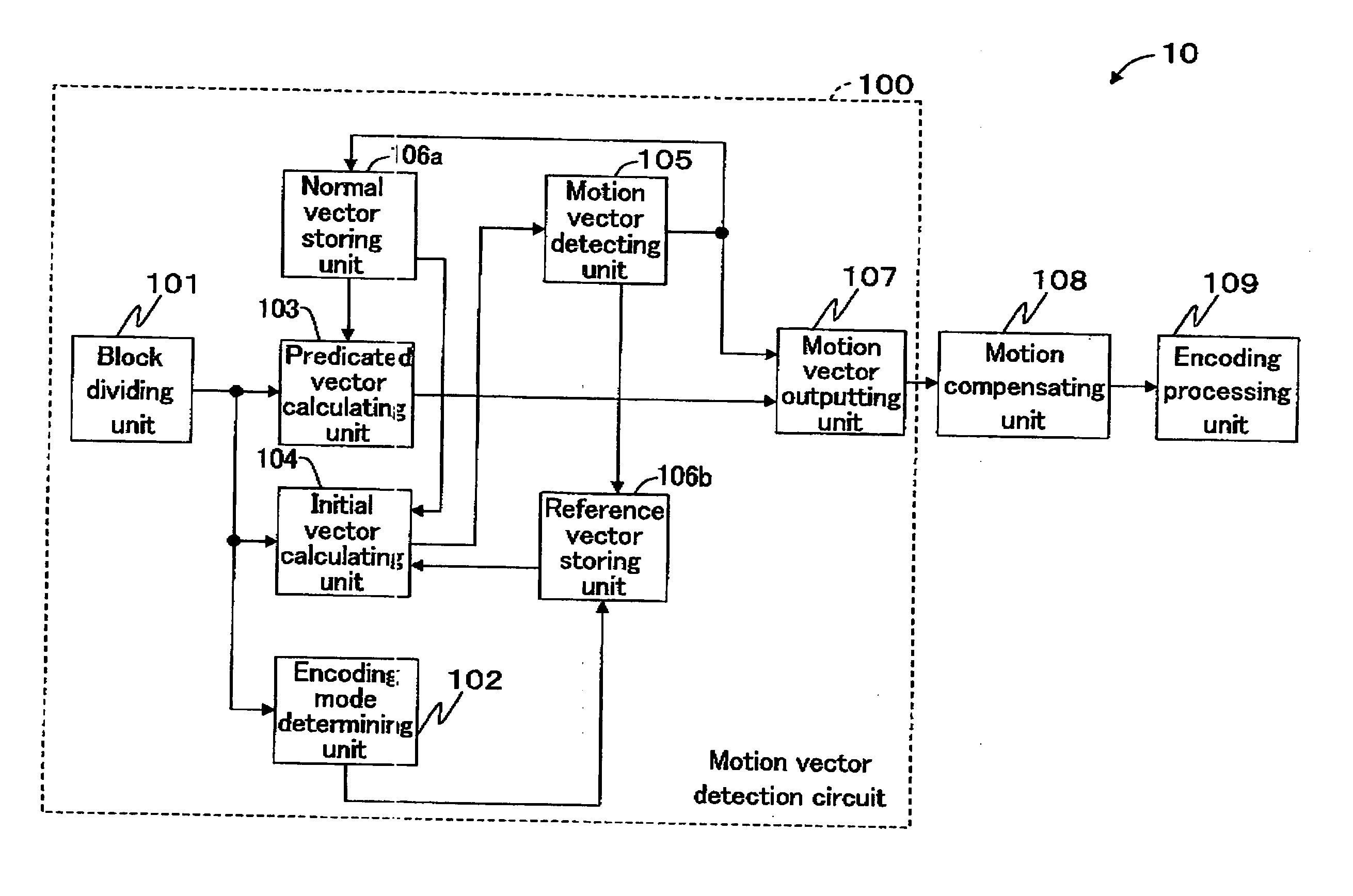
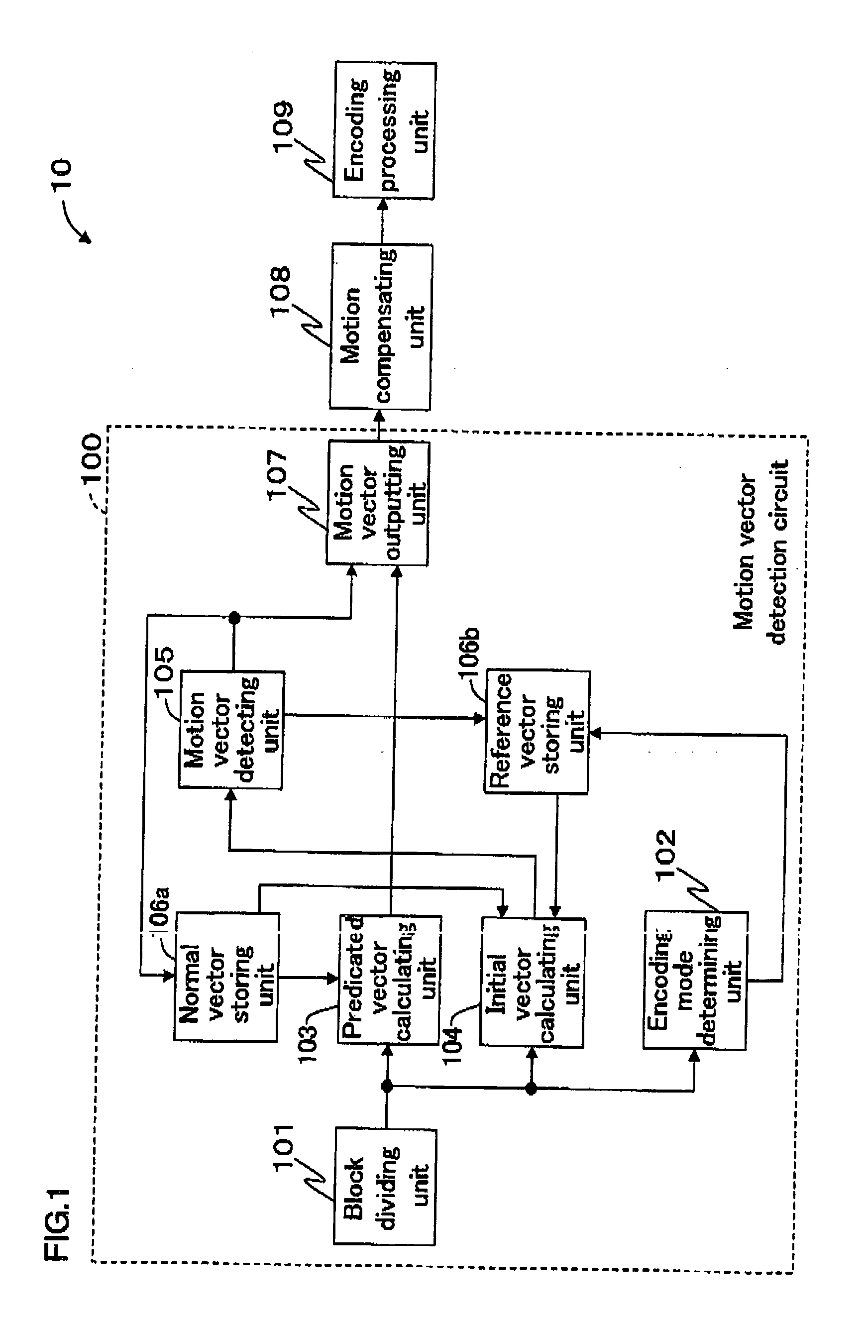
[0047]FIG. 1 is a block diagram that shows a configuration example of an image encoding circuit according to an embodiment of the present invention.

[0048] As shown in FIG. 1, an image encoding circuit 10 includes: a motion vector detection circuit 100; a motion compensating unit 108; and an encoding processing unit 109.

[0049] The motion vector detection circuit 100 includes: a block dividing unit 101; an encoding mode determining unit 102; a predicted vector calculating unit 103; an initial vector calculating unit 104; a motion vector detecting unit 105; a normal vector storing unit 106a and a reference vector storing unit 106b that together serve as a vector storing unit, and a motion vector outputting unit 107.

[0050] The block dividing unit 101 divides an inputted image into blocks each having a predetermined size, and assigns a...


PUM


Abstract

The vector detecting unit detects a motion vector even for a block that is encoded in the intra mode, and the detected motion vector is stored in the reference vector storing unit. Even for a block that has been encoded in the intra mode, the initial vector calculating unit calculates an initial point with the use of a reference vector, the initial point serving as an initial point used in a motion vector detection process during hierarchical block matching. Thus, it is possible to calculate an initial point with a high precision level with the use of motion information from the vicinity of a target block for which a motion vector is to be detected.

Description

[0001] This Nonprovisional application claims priority under 35 U.S.C. §119(a) on Patent Application No. 2004-196140 filed in Japan on Jul. 1, 2004, the entire contents of which are hereby incorporated by reference. BACKGROUND OF THE INVENTION [0002] 1. Field of the Invention [0003] The present invention relates to a motion vector detection circuit for detecting a motion vector using a predetermined method such as a three-step method and a hierarchical search method, an image encoding circuit using the motion vector detection circuit, a motion vector detection method, and an image encoding method using the motion vector detection method. [0004] 2. Description of the Related Art [0005] Conventionally, a reference pixel used in the encoding process of a still image is a pixel that has already been encoded in the image. Such an encoding process is referred to as the intra mode (or the intra-frame prediction encoding). On the other hand, in the case of a moving image, a pixel in a previ...

Claims


Application Information

Patent Timeline
Patent Type & Authority Applications(United States)
IPC IPC(8): H04N11/04H04N19/50H04N19/105H04N19/134H04N19/139H04N19/176H04N19/189H04N19/503H04N19/51H04N19/533H04N19/56H04N19/61H04N19/625H04N19/91
CPCH04N5/145H04N19/53H04N19/159
Inventor SAKURAI, RYOJI
Owner SHARP KK
Why Eureka
Try Eureka