Fixed shaft type fluid dynamic bearing motor

Inactive Publication Date: 2006-01-05
KURA LABORATRIES CORP
View PDF6 Cites 32 Cited by
  • Summary
  • Abstract
  • Description
  • Claims
  • Application Information

AI Technical Summary

Benefits of technology

[0033] According to still another aspect of the embodiment, the fluid dynamic bearing motor facilitates control of the amount of lubricating fluid to be filled into the bearing and also eliminates the impacts on rotational balance ascribable to uneven distribution and

Problems solved by technology

However, such fluid dynamic bearing is suffering from a number of disadvantages, for example, it could be sensitive to external vibration, imbalances and shock.
All of the known fluid dynamic bearing designs for a motor attached at both ends has not been easy to realize.
Opening a motor at both ends greatly increases the risk of oil leakage out of the fluid dynamic bearing.
This leakage is caused by, among other things, small differences in net flow rate created by differing pumping pressures in the bearing.
Moreover, due to manufacturing imperfections of the bearing, the gap in the bearing may not be uniform along its length and this can create pressure imbalance in the bearing and hence, cause leakage when both ends of the fluid dynamic bearing are open.
Thus, it is difficult to employ t

Method used


Image

  • Fixed shaft type fluid dynamic bearing motor
  • Fixed shaft type fluid dynamic bearing motor
  • Fixed shaft type fluid dynamic bearing motor

Examples


first embodiment

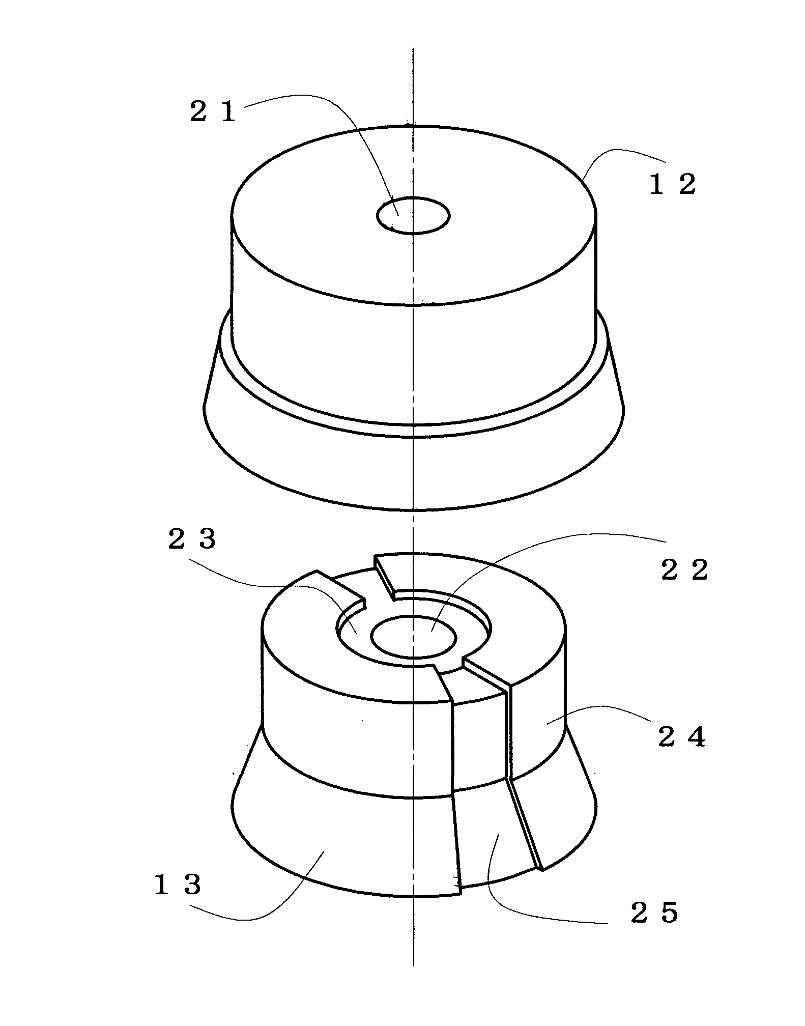
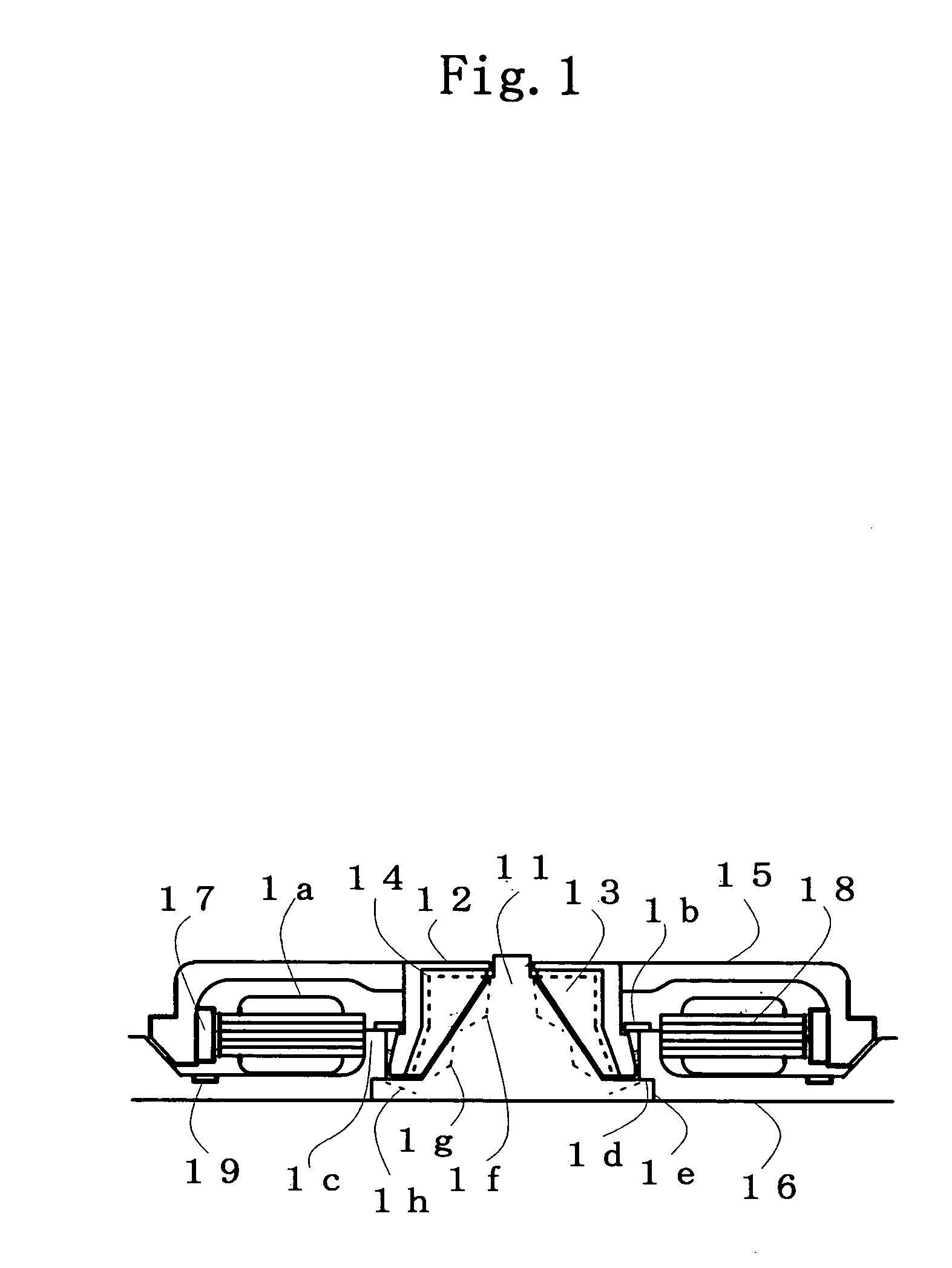
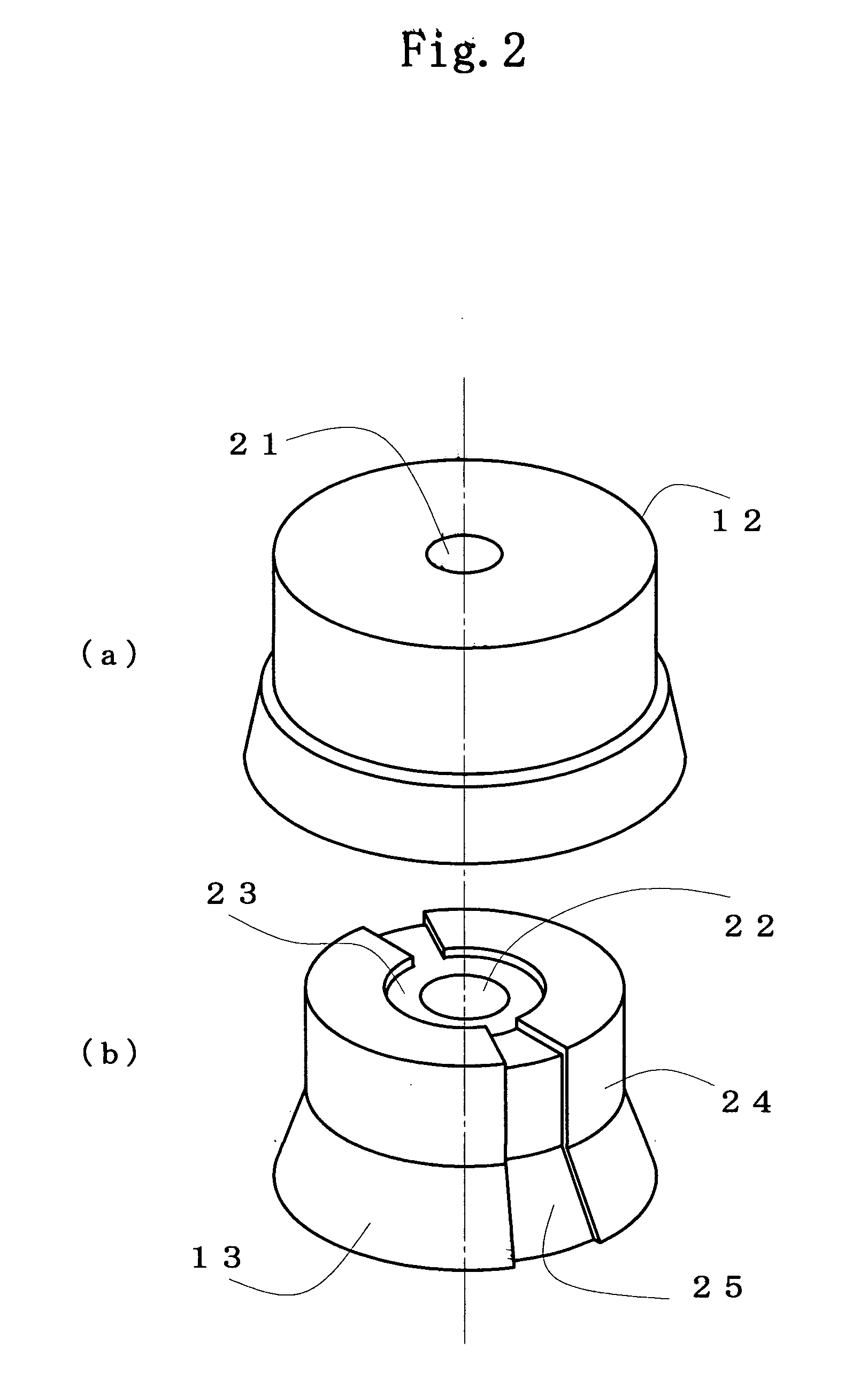
[0049]FIG. 1 is a vertical sectional view of a fixed shaft type fluid dynamic bearing motor which is the present invention. A fixed shaft (hereinafter, referred to as a conical shaft 11 or a shaft 11) includes a truncated cone shape side wall diminishing its diameter toward an end of the shaft. A sleeve is composed of an outer member 12 and an inner member 13. The inner member 13 has an inner wall forming a conical concavity accommodating the shaft 11 and surrounding the side wall, the inner wall opposing the wall of the shaft 11 with a clearance. The shaft 11 is positioned to a base plate 16 by using its radial side 1e at the bottom end, and is fixed to the base plate 16 with its axial side 1d being secured with a suitable adhesive strength.

[0050] To attract the rotating part, including the outer member 12 and the inner member 13, magnetically along the axial direction, magnetic pieces 19 are embedded in the base plates 16 so as to face rotor magnets 17. The numerals 15, 18, and 1a...

third embodiment

[0137] For a fourth embodiment of the present invention, description will be given of an example where a low-profile HDD is formed. FIGS. 13(a) and 13(b) show an example of configuration of the low-profile HDD which is formed by incorporating the present invention, or the fluid dynamic bearing motor of the fixed shaft structure of FIG. 8.

[0138] The low-profile HDD shown in FIG. 13(a) has a fluid dynamic bearing motor 136 of fixed shaft structure which is formed on a case 131, or on the base plate 16. A magnetic disk 133 is loaded on the motor 136. An actuator 135 for positioning a magnetic head 134 at a predetermined position on the magnetic disk 133 is provided. A cover 132 is fixed to the case 131. The shaft 61 makes contact with the cover 132 from below, thereby supporting the cover 132. None of electronic circuits and filter mechanisms for controlling the environment inside the HDD is shown.

[0139] In FIGS. 13(a) and 13(b), the fluid dynamic bearing motor 136 is shown with the i...


PUM


Abstract

A fixed shaft type fluid dynamic bearing motor having two interfaces of a lubricating fluid. A channel leading from near the top end of the inner periphery of a rotating sleeve to near the periphery of the bottom of the sleeve is formed in the sleeve. The lubricating fluid flows into the channel by centrifugal force, and further conveyed to near the periphery of the bottom of the sleeve by centrifugal force and/or by slanted channel in circumferential direction. A dynamic-pressure generating groove for pumping the lubricating fluid toward the top end of the sleeve is formed between the fixed shaft and the sleeve. The dynamic-pressure generating groove and the centrifugal force cause the circulation of the lubricating fluid, thereby sealing the lubricating fluid. A cone bearing or a cylindrical bearing can be used for bearing configuration. Also, the axial space smaller than that of tapered seals can be utilized.

Description

BACKGROUND OF THE INVENTION [0001] 1. Field of the Invention [0002] The invention relates to a fluid dynamic bearing motor for a recording disk drive, and more particularly to a fixed shaft type fluid dynamic bearing motor which uses a novel lubricating fluid sealing structure as an alternative to conventional tapered seals. [0003] 2. Description of the Related Art [0004] The dominant bearing structure in conventional fluid dynamic bearing motors for magnetic disk drives (HDDs) has been a rotating shaft structure in which a lubricating fluid and air form only a single interface to facilitate sealing in the lubricating fluid. However, such fluid dynamic bearing is suffering from a number of disadvantages, for example, it could be sensitive to external vibration, imbalances and shock. [0005] A desirable solution to this problem would be to have the spindle motor attached to both the base and the top cover of the disk drive housing. This would increase overall drive performance. A moto...

Claims


Application Information

Patent Timeline
IPC IPC(8): F16C32/06
CPCF16C17/102F16C17/107F16C33/74F16C33/1085F16C33/107F16C33/743F16C2370/12
Inventor ICHIYAMA, YOSHIKAZU
Owner KURA LABORATRIES CORP
Why Eureka
Try Eureka