Broadband ultra-flattened dispersion micro-structured fiber

a micro-structured fiber and ultra-flattened technology, applied in the field of micro-structured fibers, can solve the problems of increasing the difficulty of manufacture and manufacturing cost, reducing the ring number of air holes, and complicated design procedures, so as to improve the shortcomings of high manufacture difficulty and high confinement loss, reduce the diameter of air holes, and increase the pitch

Inactive Publication Date: 2006-01-05
NAT SUN YAT SEN UNIV
View PDF3 Cites 7 Cited by
  • Summary
  • Abstract
  • Description
  • Claims
  • Application Information

AI Technical Summary

Benefits of technology

[0010] One objective of the present invention is to improve the shortcomings of high manufacture difficulty and high confinement loss of the conventional micro-structured fiber caused by reducing the diameter of the air holes and enlarging the pitch between the air holes when being designed in the consideration of flattened dispersion. The micro-structured fiber of the present invention has the advantages of broader band of nearly zero dispersion, less confinement loss, being easier to design due to less geometrical parameters needed to be optimized, and being easier to fabricate.

Problems solved by technology

Therefore, such design raises the difficulty in manufacture and the manufacturing cost (see “A.
This design significantly reduces the ring number of the air holes, but the design procedure becomes complicated due to several geometrical parameters, five (four kinds of air-hole diameters and one pitch) for the four-ring case and six (five kinds of air-hole diameters and one pitch) for the five-ring case, which are needed to be simultaneously optimized to achieve the flattened dispersion behavior of the PCF.

Method used


Image

  • Broadband ultra-flattened dispersion micro-structured fiber
  • Broadband ultra-flattened dispersion micro-structured fiber
  • Broadband ultra-flattened dispersion micro-structured fiber

Examples


Embodiment Construction

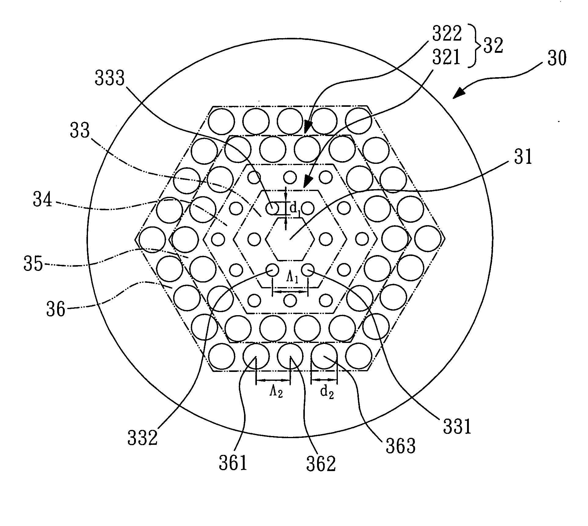
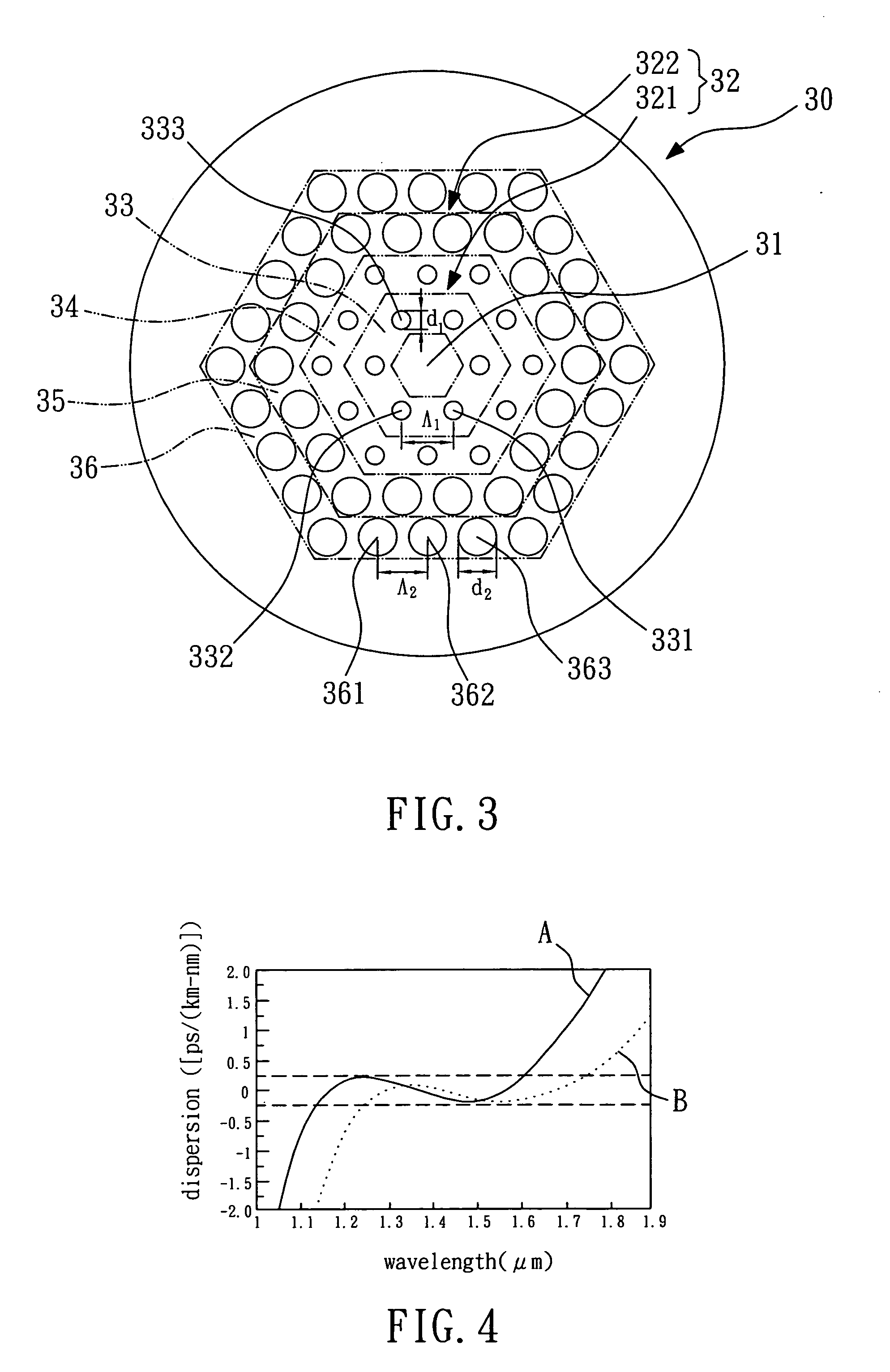
[0016]FIG. 3 shows a schematic cross-sectional view of a micro-structured fiber according to a preferred embodiment of the present invention. The micro-structured fiber 30 comprises a core region 31 and a cladding region 32, wherein the core region 31 and the cladding region 32 have the same material, such as silica. The cladding region 32 has a plurality of air holes 331, 332, 333 that are regularly arranged on a plurality of hexagonal rings 33, 34, 35, 36, wherein the innermost ring 33 of the fiber 30 defines the core region 31. That is, in the present invention, the regularly arrayed air holes 331, 332, 333 in the innermost ring 33 surround the central portion of the silica fiber 30 to form the core region 31. Therefore, the core region 31 of the fiber 30 of the present invention has no air hole. The region that has a plurality of regularly arrayed air holes is the cladding region 32. In this embodiment, the rings are equilateral hexagons from top view.

[0017] The characteristic ...


PUM


Abstract

The invention relates to a micro-structured fiber comprising a core region and a cladding region. The cladding region has a plurality of air holes regularly arranged on a plurality of rings, wherein the innermost ring of the fiber defines the core region. The cladding region comprises an inner circumference portion and an outer circumference portion; the inner circumference portion comprises at least one ring, the outer circumference portion comprises at least one ring, wherein the diameter of the air hole on the outer circumference portion is larger than that of the air hole on the inner circumference portion. As a result, the micro-structured fiber of the present invention has the advantages of broader band of nearly zero dispersion, less confinement loss, being easier to design due to less geometrical parameters needed to be optimized, and being easier to fabricate.

Description

BACKGROUND OF THE INVENTION [0001] 1. Field of the invention [0002] The present invention relates to a micro-structured fiber having an array of micrometer-sized air holes, and more particularly, to a micro-structured fiber having a plurality of air holes with different diameters. [0003] 2. Description of the Related Art [0004] Referring to FIG. 1, a cross-sectional view of a conventional micro-structured fiber is shown. The micro-structured fiber 10 is a so-called photonic crystal fiber (PCF). As shown in FIG. 1, the micro-structured fiber 10 comprises a core region 11 and a cladding region 12, wherein the material of the core region 11 is the same as that of the cladding region 12. The cladding region 12 has a plurality of air holes 13 that are approximately circular in shape and are regularly arranged on a plurality of hexagonal rings 14. The innermost ring 14 of the fiber 10 defines the core region 11. All of the air holes 133 have the same diameter d, and the pitches (distances...

Claims


Application Information

Patent Timeline
Patent Type & Authority Applications(United States)
IPC IPC(8): G02B6/02G02B6/00
CPCG02B6/02233G02B6/02361G02B6/02357
Inventor WU, TZONG-LINCHAO, CHIA-HSIN
Owner NAT SUN YAT SEN UNIV
Why Eureka
Try Eureka