Flow modulation devices

a technology of flow modulation and flow control, which is applied in the direction of instruments, chemical methods analysis, material testing goods, etc., can solve the problems of complexity, increased manufacturing cost, and risk of valve failure, and the requirement to initiate flow through the valve. , the effect of relatively low cos

Inactive Publication Date: 2006-01-05
LIFESCAN SCOTLAND
View PDF78 Cites 72 Cited by
  • Summary
  • Abstract
  • Description
  • Claims
  • Application Information

AI Technical Summary

Benefits of technology

[0004] Devices for modulating the flow of a liquid are provided. Embodiments of the subject devices include a flow modulation pathway having a hydrophobic region in contact with a capillary passage that includes at least one stepped-down junction. In certain embodiments, a subject device may be formed by two contacted substrates and the capillary passage provided therebetw

Problems solved by technology

Conventional valves used in microfluidic devices may be complex, which complexity may increase manufacturing costs the risk of valve failure.
Furthermore

Method used


Image

  • Flow modulation devices
  • Flow modulation devices
  • Flow modulation devices

Examples


Embodiment Construction

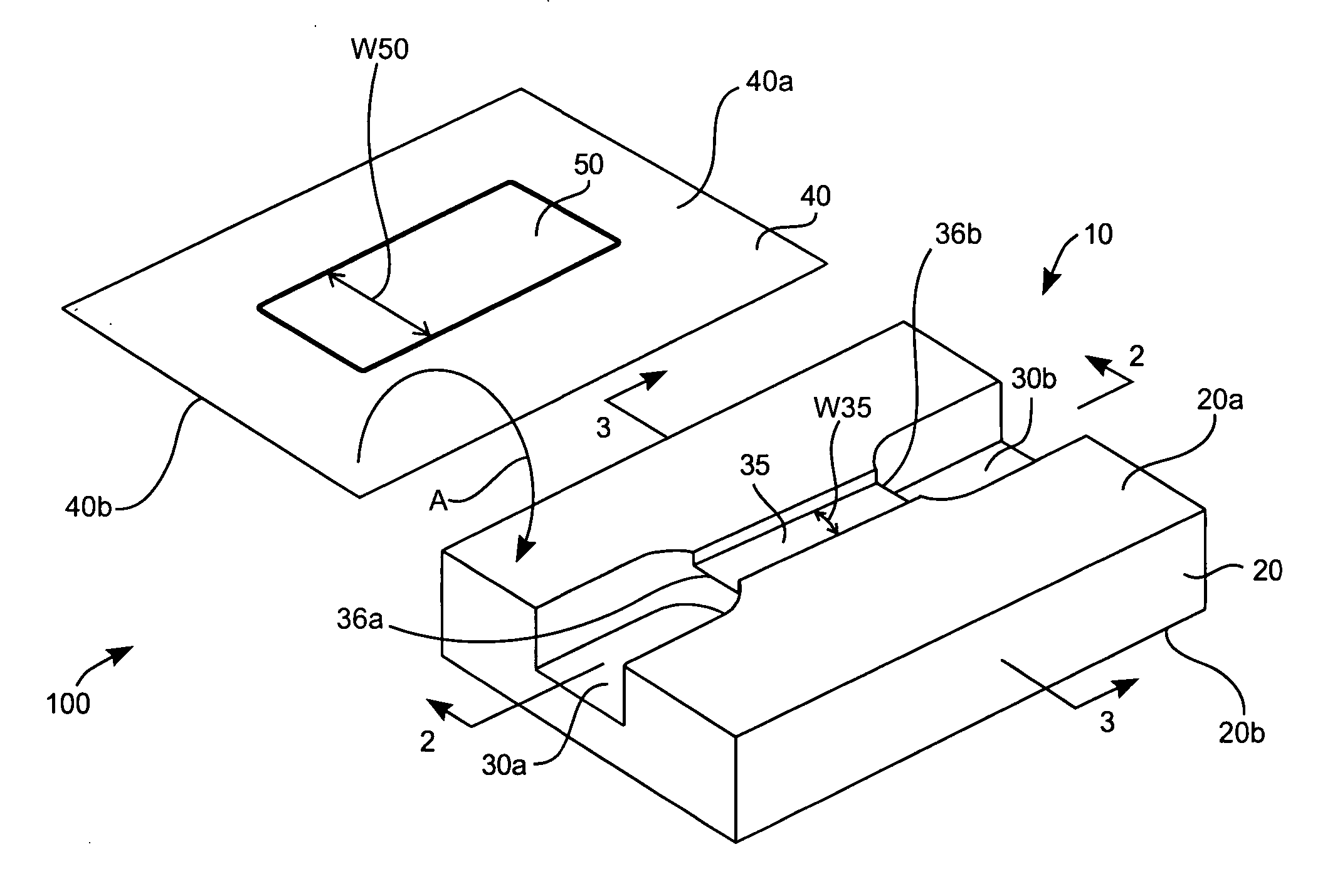
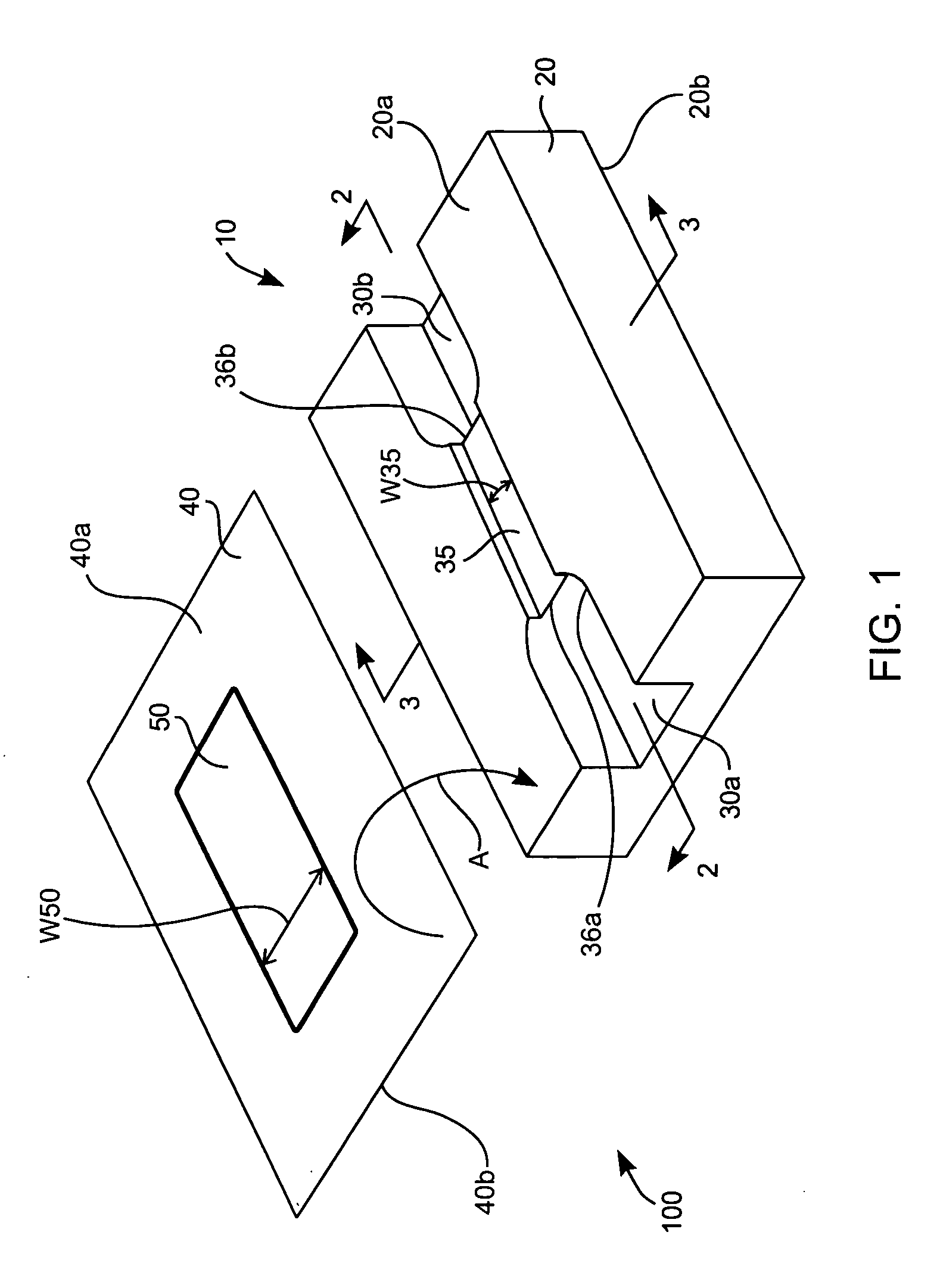
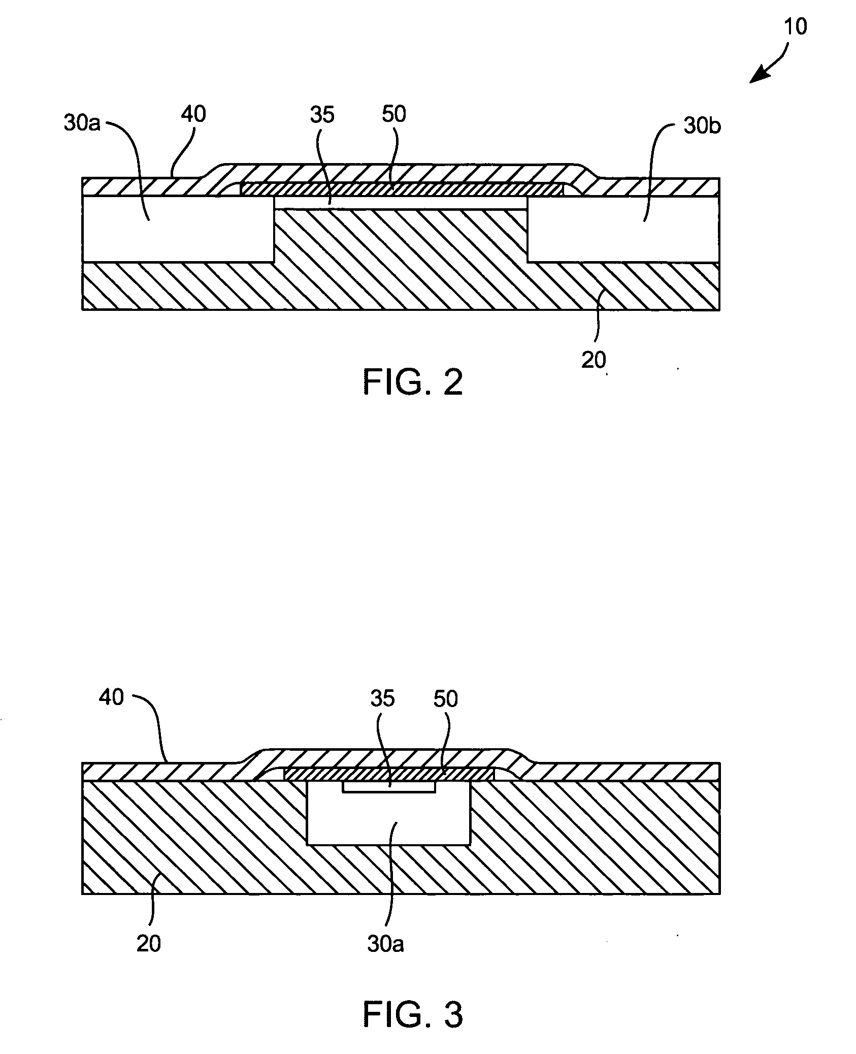
[0012] Devices for modulating the flow of a liquid are provided. Embodiments of the subject devices include a flow modulation pathway having a hydrophobic region in contact with a capillary passage that includes at least one stepped-down junction. In certain embodiments, a subject device may be formed by two contacted substrates and the capillary passage provided therebetween. In certain embodiments, the capillary passage may be formed by a trench in one or more of the substrates. In certain embodiments, the capillary passage may be formed by a spacer present between the two substrates. Embodiments of the subject invention may also include sharp edges at one or more stepped-down junction. Also provided are kits that include a subject device.

[0013] Before the present invention is described, it is to be understood that this invention is not limited to particular embodiments described, as such may, of course, vary. It is also to be understood that the terminology used herein is for th...


PUM


Abstract

Devices and kits for modulating the flow of a liquid are provided.

Description

BACKGROUND OF THE INVENTION [0001] Valves are used in a variety of applications in which it is desirable to control the flow of liquid along a liquid flow path. For example, valves are used to control liquid flow in pharmaceutical applications, biotechnology applications, life sciences applications, biomedical applications, public health applications, agriculture applications, etc. [0002] Depending on the system and flow volumes, valves may range in size from very large to very small. For example, one application in which valves are employed is the area of microfluidics, which broadly refers to technologies that control the flow of minute amounts of liquids in miniaturized systems. For example, microfluidic devices for the sampling and analysis of biological liquids requires miniature valves to control liquid flow in the device. Conventional valves used in microfluidic devices may be complex, which complexity may increase manufacturing costs the risk of valve failure. Furthermore, t...

Claims


Application Information

Patent Timeline
IPC IPC(8): G01N21/00B01L3/00F15C5/00F16K99/00
CPCB01L3/502738B01L2200/12F16K99/0017F16K99/0001B01L2400/0688F15D1/08F15D1/14
Inventor BOHM, SEBASTIANMCNEILAGE, ALAN WATSON
Owner LIFESCAN SCOTLAND
Why Eureka
Try Eureka