[0012] In such a way, since only the channel information of the prescribed channel is stored in the memory and the prescribed channel is set as the receiving channel, irrespective of whether or not the directive direction of the directivity switching antenna in which the broadcasting of the prescribed channel can be most preferably received can be specified, a time required for setting the channel can be shortened. Then, when the prescribed channel is set as described above, the prescribed channel is subsequently selected. At this time, since the
direction information of the directivity switching antenna corresponding to the prescribed channel is not stored in the memory, while the directive direction of the directivity switching antenna is immediately switched, the direction in which the broadcasting of the prescribed channel can be most preferably received can be searched without being restricted by the information stored in the memory. Further, a time required until the broadcasting can be looked at and listened to in a most preferable state can be shortened.
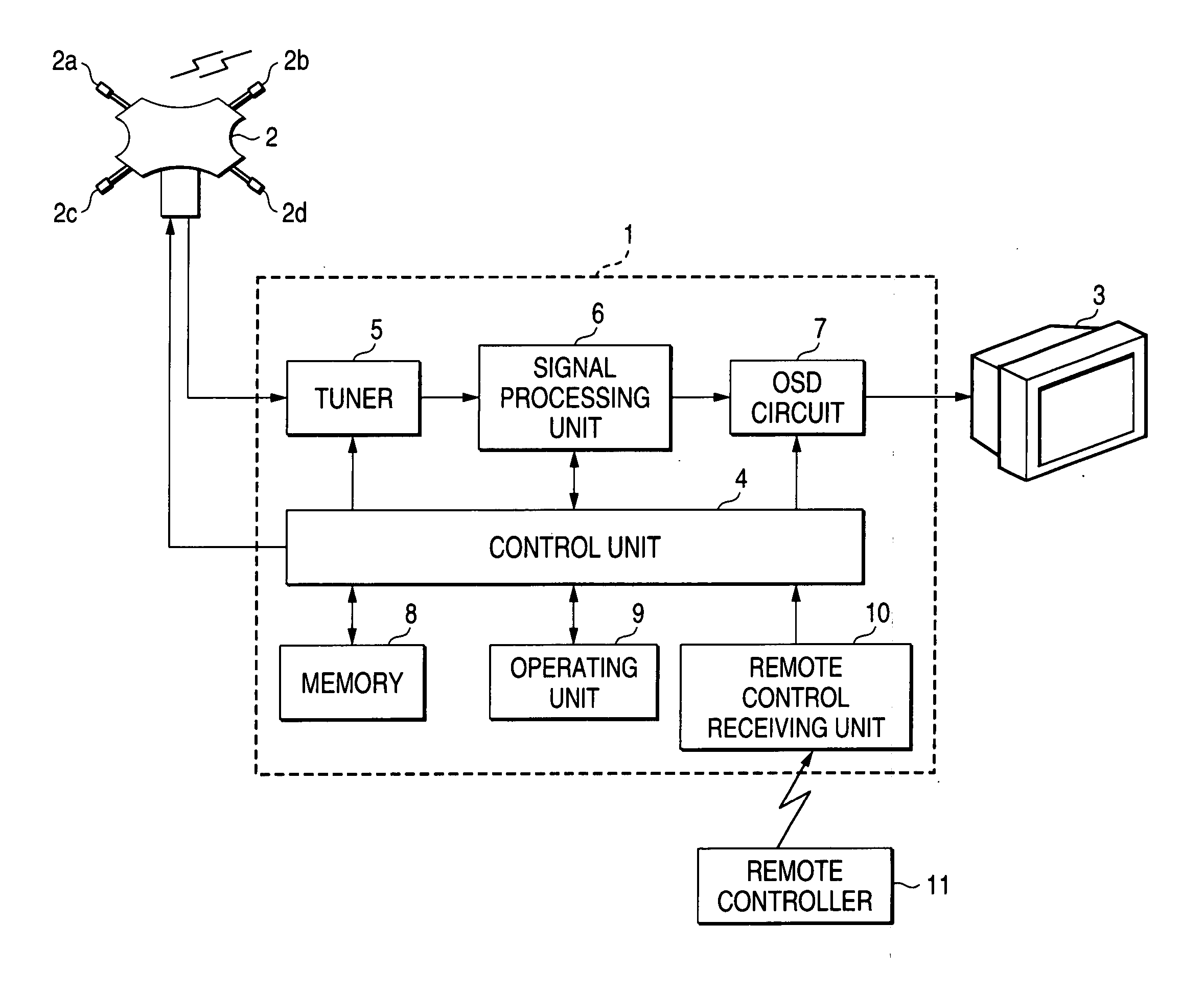
[0018] In such a way, the directive direction of the directivity switching antenna is automatically switched and the direction in which the broadcasting of the prescribed channel can be most preferably received is specified. Accordingly, a labor necessary for the user who switches the directive direction of the directivity switching antenna to specify the direction in which the broadcasting can be most preferably received can be saved. Thus, a time required for specifying the direction in which the broadcasting can be most preferably received can be more shortened than that required by the user. Further, since the reproducing unit is allowed to reproduce the broadcasting received by the directivity switching antenna at any time, the user can recognize the reproducing state of the broadcasting of the prescribed channel from the reproducing state to grasp whether or not the direction in which the broadcasting can be most preferably received can be specified. Therefore, the user can readily decide whether or not the
direction information of the directivity switching antenna is stored and can easily designate the directive direction to be stored. Thus, a time required for setting the prescribed channel can be more shortened. Further, only the channel information of the prescribed channel is stored in the memory to set the prescribed channel. In this case, when the prescribed channel is subsequently selected, while the directive direction of the directivity switching antenna is immediately and automatically switched, the direction in which the broadcasting of the prescribed channel can be most preferably received can be searched. Thus, a time necessary until the broadcasting of the prescribed channel can be looked at and listened to in a most preferable state can be more shortened.
[0020] In such a way, the user can recognize the directive direction to which the directivity switching antenna is actually directed and can grasp whether or not the direction in which the broadcasting of the prescribed channel can be most preferably received can be specified on the basis of whether or not the displayed directive direction is secured to one direction. Therefore, the user can readily decide whether or not the direction information of the directivity switching antenna is stored and can easily designate the directive direction to be stored. Thus, a time required for setting the prescribed channel can be more shortened.
[0022] In such a way, since the user can instruct whether or not the direction information of the
smart antenna is stored, when the prescribed channel is set as the receiving channel, if the directive direction in which the broadcasting of the prescribed channel can be most preferably received is specified, the direction information is instructed to be stored. Thus, the channel information of the prescribed channel can be correlated with the direction information showing the specified directive direction to store the correlated information in the memory so that the prescribed channel can be set. Then, when the prescribed channel is set as described above, the prescribed channel is subsequently selected. At this time, since the direction information corresponding to the prescribed channel is stored in the memory, the directive direction of the
smart antenna is switched to the direction shown by the direction information. Thus, the broadcasting of the prescribed channel can be immediately received in a most preferable way and a time required until the broadcasting can be looked at and listened to in a most preferable state can be shortened. On the other hand, when the prescribed channel is set as the receiving channel, if the directive direction in which the broadcasting of the prescribed channel can be most preferably received cannot be specified, the direction information is instructed not to be stored. Thus, only the channel information of the prescribed channel is stored in the memory so that the prescribed channel can be set as the receiving channel and the time required until the prescribed channel is set as the receiving channel can be shortened. Then, when the prescribed channel is set as described above, the prescribed channel is subsequently selected. At this time, since the direction information corresponding to the prescribed channel is not stored in the memory, while the directive direction of the
smart antenna is immediately switched, the direction in which the broadcasting of the prescribed channel can be most preferably received can be searched without being restricted by the information stored in the memory. Further, a time required until the broadcasting can be looked at and listened to in a most preferable state can be shortened.
[0023] According to the present invention, since only the channel information of the prescribed channel is stored in the memory and the prescribed channel is set as the receiving channel, the time required for setting the prescribed channel as the receiving channel can be shortened. Then, when the set prescribed channel is subsequently selected, since the direction information of the directivity switching antenna corresponding to the prescribed channel is not stored in the memory, while the directive direction of the directivity switching antenna is immediately switched, the direction in which the broadcasting of the prescribed channel can be most preferably received can be searched without being restricted by the information stored in the memory. Further, a time required until the broadcasting can be looked at and listened to in a most preferable state can be shortened.

